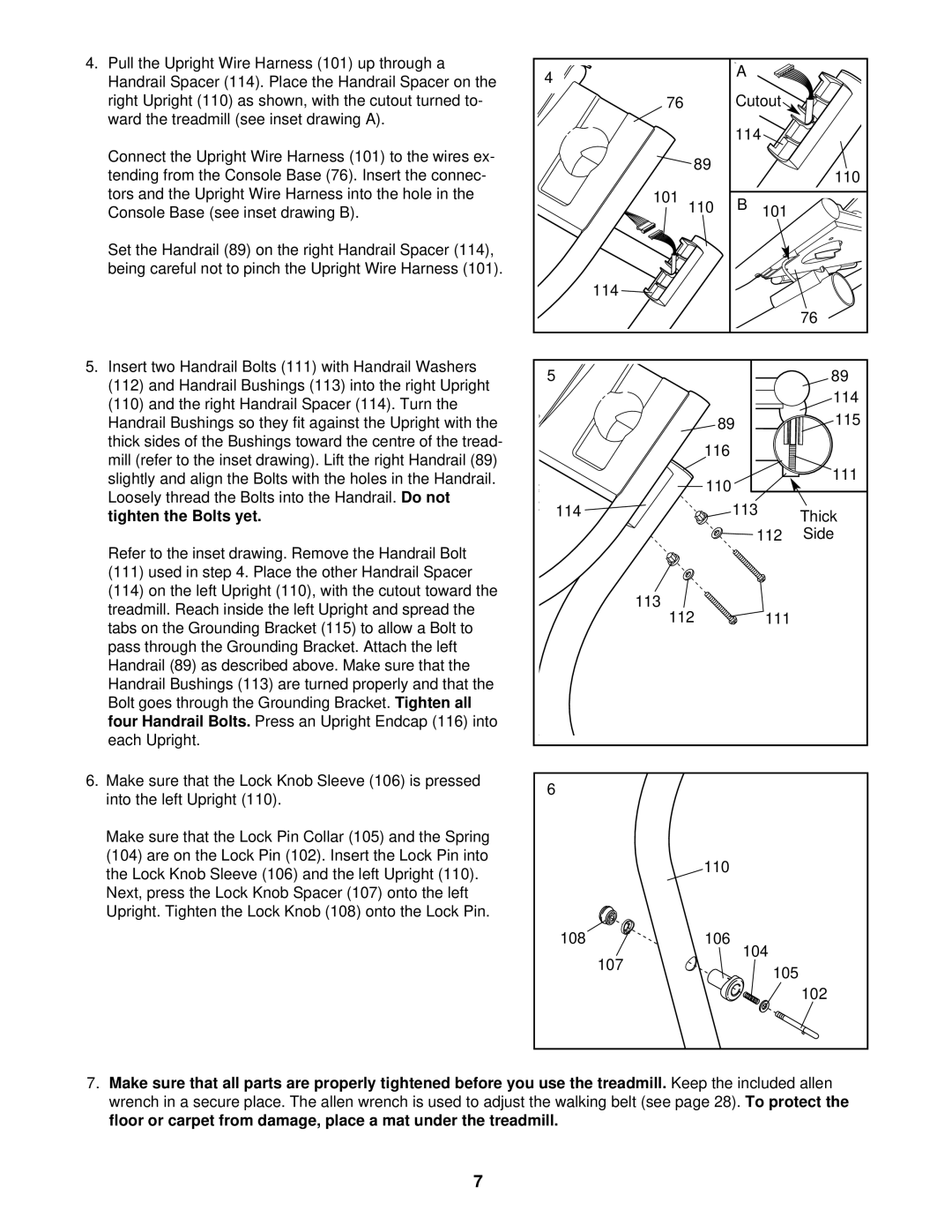
4. Pull the Upright Wire Harness (101) up through a | 4 |
|
| A |
|
|
Handrail Spacer (114). Place the Handrail Spacer on the |
|
|
|
| ||
|
|
|
|
| ||
right Upright (110) as shown, with the cutout turned to- |
| 76 |
| Cutout |
| |
ward the treadmill (see inset drawing A). |
|
|
| 114 |
|
|
|
|
|
|
|
| |
Connect the Upright Wire Harness (101) to the wires ex- |
|
| 89 |
|
|
|
tending from the Console Base (76). Insert the connec- |
|
|
|
| 110 | |
|
|
|
|
| ||
tors and the Upright Wire Harness into the hole in the |
| 101 | 110 | B | 101 |
|
Console Base (see inset drawing B). |
|
| ||||
Set the Handrail (89) on the right Handrail Spacer (114), |
|
|
|
|
|
|
being careful not to pinch the Upright Wire Harness (101). |
|
|
|
|
|
|
|
| 114 |
|
|
|
|
|
|
|
|
|
| 76 |
5. Insert two Handrail Bolts (111) with Handrail Washers | 5 |
|
|
|
| 89 |
(112) and Handrail Bushings (113) into the right Upright |
|
|
|
| ||
|
|
|
|
| 114 | |
(110) and the right Handrail Spacer (114). Turn the |
|
|
|
|
| |
|
|
|
|
| 115 | |
Handrail Bushings so they fit against the Upright with the |
|
| 89 |
|
| |
thick sides of the Bushings toward the centre of the tread- |
|
| 116 |
|
|
|
mill (refer to the inset drawing). Lift the right Handrail (89) |
|
|
|
|
| |
|
|
|
|
| 111 | |
slightly and align the Bolts with the holes in the Handrail. |
|
| 110 |
|
| |
Loosely thread the Bolts into the Handrail. Do not |
|
|
|
|
| |
114 |
| 113 |
|
| ||
tighten the Bolts yet. |
|
| Thick | |||
|
|
|
|
| ||
|
|
|
| 112 | Side | |
Refer to the inset drawing. Remove the Handrail Bolt |
|
|
|
|
|
|
(111) used in step 4. Place the other Handrail Spacer |
|
|
|
|
|
|
(114) on the left Upright (110), with the cutout toward the |
| 113 |
|
|
|
|
treadmill. Reach inside the left Upright and spread the |
|
|
|
|
| |
| 112 |
| 111 |
| ||
tabs on the Grounding Bracket (115) to allow a Bolt to |
|
|
| |||
|
|
|
|
|
| |
pass through the Grounding Bracket. Attach the left |
|
|
|
|
|
|
Handrail (89) as described above. Make sure that the |
|
|
|
|
|
|
Handrail Bushings (113) are turned properly and that the |
|
|
|
|
|
|
Bolt goes through the Grounding Bracket. Tighten all |
|
|
|
|
|
|
four Handrail Bolts. Press an Upright Endcap (116) into |
|
|
|
|
|
|
each Upright. |
|
|
|
|
|
|
6. Make sure that the Lock Knob Sleeve (106) is pressed | 6 |
|
|
|
|
|
into the left Upright (110). |
|
|
|
|
| |
|
|
|
|
|
| |
Make sure that the Lock Pin Collar (105) and the Spring |
|
|
|
|
|
|
(104) are on the Lock Pin (102). Insert the Lock Pin into |
|
| 110 |
|
|
|
the Lock Knob Sleeve (106) and the left Upright (110). |
|
|
|
|
| |
|
|
|
|
|
| |
Next, press the Lock Knob Spacer (107) onto the left |
|
|
|
|
|
|
Upright. Tighten the Lock Knob (108) onto the Lock Pin. |
|
|
|
|
|
|
| 108 |
| 106 | 104 |
| |
|
| 107 |
|
| ||
|
|
|
| 105 |
| |
|
|
|
|
|
| |
|
|
|
|
|
| 102 |
7.Make sure that all parts are properly tightened before you use the treadmill. Keep the included allen wrench in a secure place. The allen wrench is used to adjust the walking belt (see page 28). To protect the floor or carpet from damage, place a mat under the treadmill.
7