Cabling the Switch
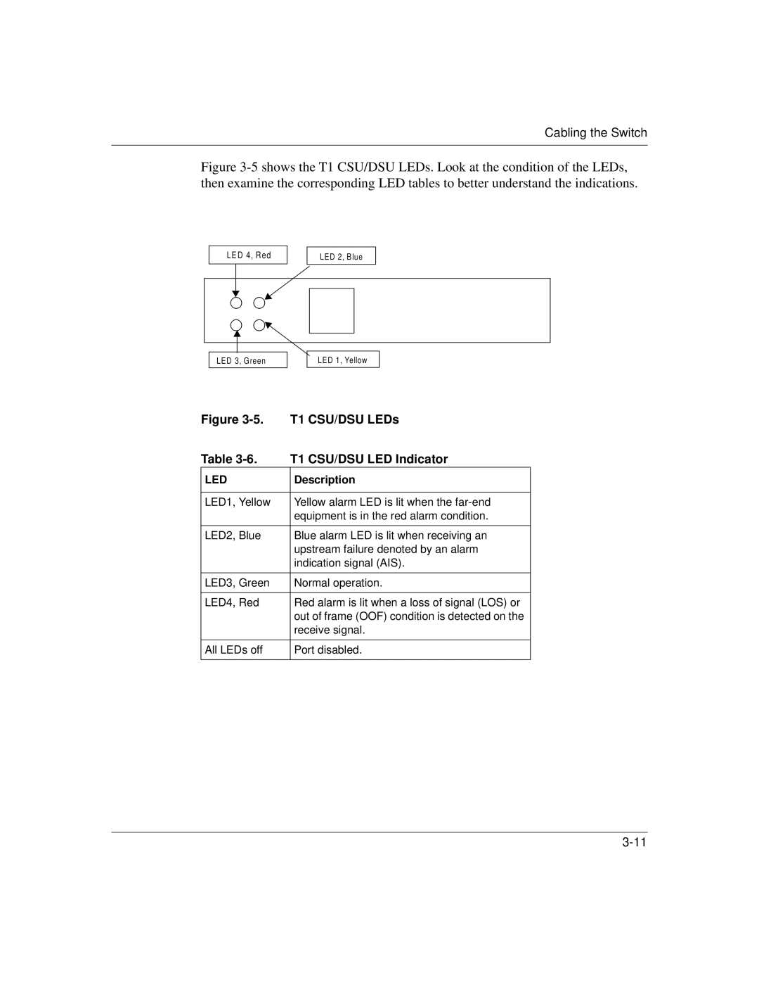
Figure 3-5 shows the T1 CSU/DSU LEDs. Look at the condition of the LEDs, then examine the corresponding LED tables to better understand the indications.
LED 4, Red
LED 2, Blue
LED 3, Green
LED 1, Yellow
Figure | T1 CSU/DSU LEDs |
Table | T1 CSU/DSU LED Indicator |
LED | Description |
|
|
LED1, Yellow | Yellow alarm LED is lit when the |
| equipment is in the red alarm condition. |
|
|
LED2, Blue | Blue alarm LED is lit when receiving an |
| upstream failure denoted by an alarm |
| indication signal (AIS). |
|
|
LED3, Green | Normal operation. |
|
|
LED4, Red | Red alarm is lit when a loss of signal (LOS) or |
| out of frame (OOF) condition is detected on the |
| receive signal. |
|
|
All LEDs off | Port disabled. |
|
|
