32 Chapter 3 Instant Internet 400 hardware installation
Switches and connectors are located on the rear panel of your unit as follows:
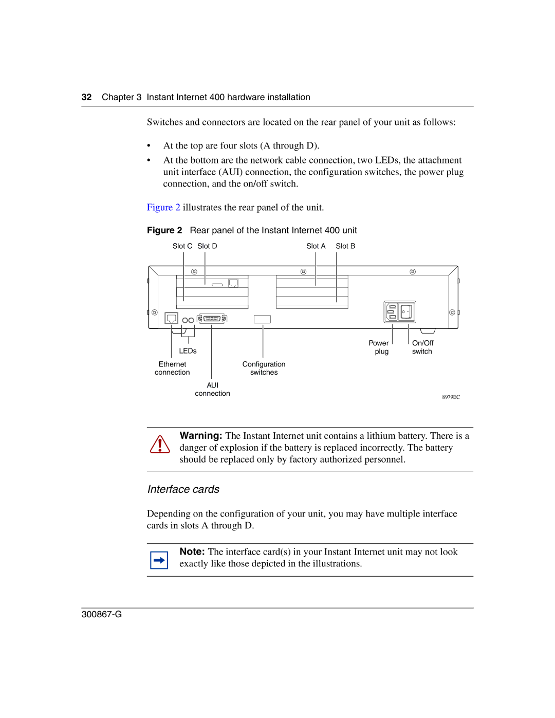
•At the top are four slots (A through D).
•At the bottom are the network cable connection, two LEDs, the attachment unit interface (AUI) connection, the configuration switches, the power plug connection, and the on/off switch.
Figure 2 illustrates the rear panel of the unit.
Figure 2 Rear panel of the Instant Internet 400 unit
Slot C Slot D | Slot A Slot B |
|
|
|
|
|
|
| Power |
|
|
|
|
|
|
| |
| LEDs |
|
| ||||
|
|
| plug | ||||
Ethernet |
| Configuration | |||||
connection |
| switches | |||||
|
|
|
| AUI |
|
| |
|
|
|
| connection |
|
| |
On/Off switch
8979EC
Warning: The Instant Internet unit contains a lithium battery. There is a danger of explosion if the battery is replaced incorrectly. The battery should be replaced only by factory authorized personnel.
Interface cards
Depending on the configuration of your unit, you may have multiple interface cards in slots A through D.
Note: The interface card(s) in your Instant Internet unit may not look exactly like those depicted in the illustrations.