Chapter 3 Instant Internet 400 hardware installation 35
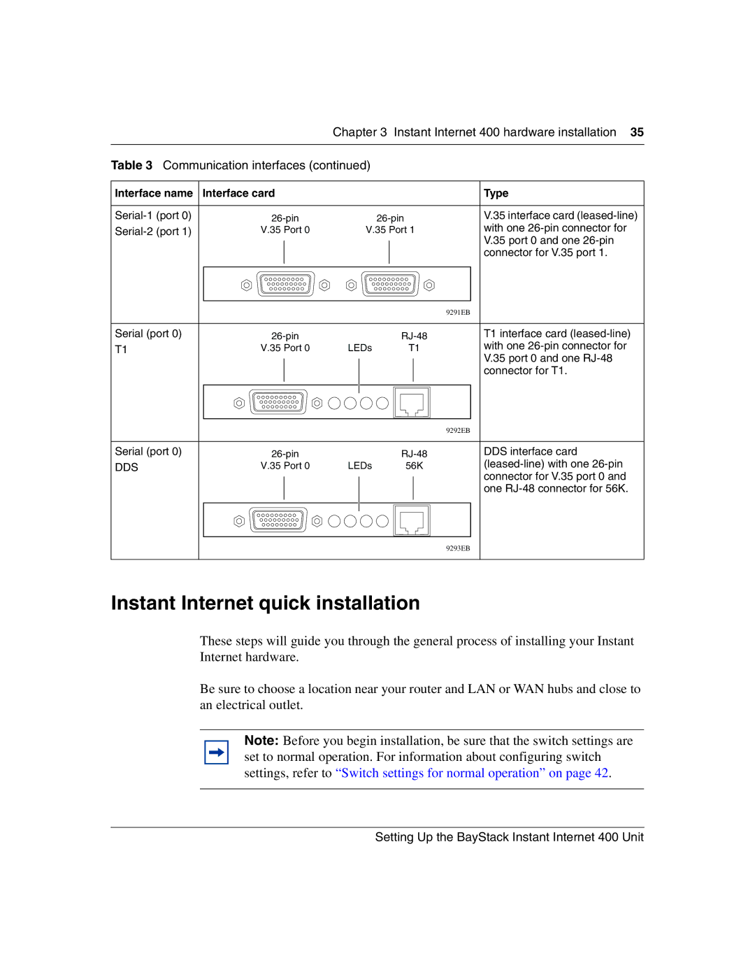
Table 3 Communication interfaces (continued)
Interface name | Interface card |
|
| Type | |
|
|
|
|
|
|
V.35 interface card | |||||
V.35 Port 0 | V.35 Port 1 | with one | |||
|
|
|
|
| V.35 port 0 and one |
|
|
|
|
| |
|
|
|
|
| connector for V.35 port 1. |
|
|
|
|
|
|
|
|
|
|
|
|
|
|
|
|
|
|
|
|
|
|
|
|
| 9291EB | |
|
|
|
|
|
|
|
|
|
Serial (port 0) |
|
|
| T1 interface card | ||||
T1 | V.35 Port 0 | LEDs | T1 |
| with one | |||
|
|
|
|
|
|
|
| V.35 port 0 and one |
|
|
|
|
|
|
|
| |
|
|
|
|
|
|
|
| connector for T1. |
|
|
|
|
|
|
|
|
|
|
|
|
|
|
|
|
|
|
|
|
|
|
|
|
|
|
|
|
|
|
|
|
|
|
|
|
|
|
|
|
|
|
| 9292EB | |
|
|
|
|
|
|
|
|
|
Serial (port 0) |
|
|
| DDS interface card | ||||
DDS | V.35 Port 0 | LEDs | 56K |
| ||||
|
|
|
|
|
|
|
| connector for V.35 port 0 and |
|
|
|
|
|
|
|
| |
|
|
|
|
|
|
|
| one |
|
|
|
|
|
|
|
|
|
|
|
|
|
|
|
|
|
|
|
|
|
|
|
|
|
|
|
|
|
|
|
|
|
|
|
|
9293EB
Instant Internet quick installation
These steps will guide you through the general process of installing your Instant Internet hardware.
Be sure to choose a location near your router and LAN or WAN hubs and close to an electrical outlet.
Note: Before you begin installation, be sure that the switch settings are set to normal operation. For information about configuring switch settings, refer to “Switch settings for normal operation” on page 42.