Installing and Operating Passport ARN Routers
Connecting to the STP Interface
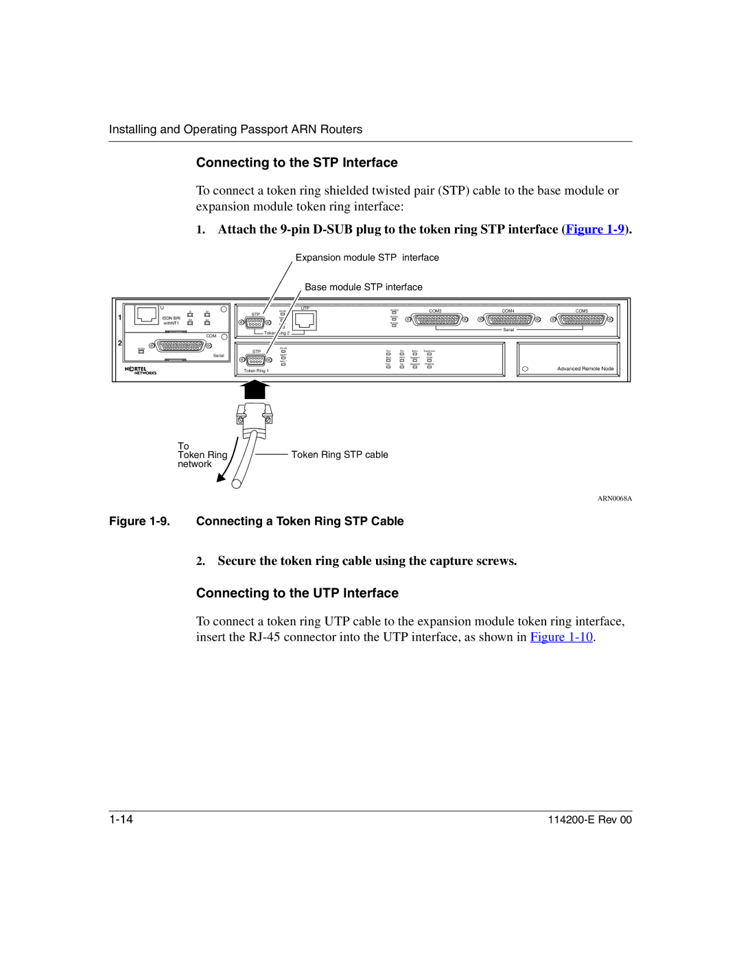
To connect a token ring shielded twisted pair (STP) cable to the base module or expansion module token ring interface:
1.Attach the
Expansion module STP interface
Base module STP interface
| U | D | B1 | RCVR | UTP | RLSD3 |
|
| COM3 | COM4 | COM5 |
|
|
|
|
|
| ||||||
1 | ISDN BRI |
|
| STP |
| RLSD4 |
|
|
|
|
|
DD | B2 | NSRT |
|
|
|
|
|
| |||
|
|
|
|
|
|
|
| ||||
| withNT1 |
|
| WFLT |
| RLSD5 |
|
|
|
|
|
|
|
|
| Token Ring 2 |
|
|
|
|
| Serial |
|
|
|
| COM |
|
|
|
|
|
|
| |
|
|
|
|
|
|
|
|
|
|
| |
2 |
|
|
|
|
|
|
|
|
|
|
|
| RLSD |
|
| RCVR |
|
|
|
|
|
|
|
|
|
|
| STP | Run | Pwr | Base | Expansion |
|
| |
|
|
| Serial |
|
|
|
|
|
|
| |
|
|
| NSRT | Boot | RPS | Adapter1 | DCM |
|
| ||
|
|
|
|
|
|
| |||||
|
|
|
| WFLT | Fail |
| Fan | Adapter2 | PCMCIA |
|
|
|
|
|
|
|
|
|
| ||||
|
|
|
| Token Ring 1 |
|
|
|
|
|
| Advanced Remote Node |
|
|
|
|
|
|
|
|
|
|
| |
To
Token RingToken Ring STP cable network
ARN0068A
Figure 1-9. Connecting a Token Ring STP Cable
2.Secure the token ring cable using the capture screws.
Connecting to the UTP Interface
To connect a token ring UTP cable to the expansion module token ring interface, insert the
