Installing and Operating Passport ARN Routers
Serial LEDs
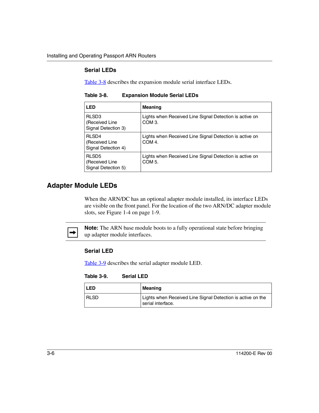
Table 3-8 describes the expansion module serial interface LEDs.
Table | Expansion Module Serial LEDs | |
|
|
|
LED |
| Meaning |
|
|
|
RLSD3 |
| Lights when Received Line Signal Detection is active on |
(Received Line |
| COM 3. |
Signal Detection 3) |
| |
|
|
|
RLSD4 |
| Lights when Received Line Signal Detection is active on |
(Received Line |
| COM 4. |
Signal Detection 4) |
| |
|
|
|
RLSD5 |
| Lights when Received Line Signal Detection is active on |
(Received Line |
| COM 5. |
Signal Detection 5) |
| |
|
|
|
Adapter Module LEDs
When the ARN/DC has an optional adapter module installed, its interface LEDs are visible on the front panel. For the location of the two ARN/DC adapter module slots, see Figure
Note: The ARN base module boots to a fully operational state before bringing up adapter module interfaces.
Serial LED
Table 3-9 describes the serial adapter module LED.
Table | Serial LED |
LED
RLSD
Meaning
Lights when Received Line Signal Detection is active on the serial interface.
