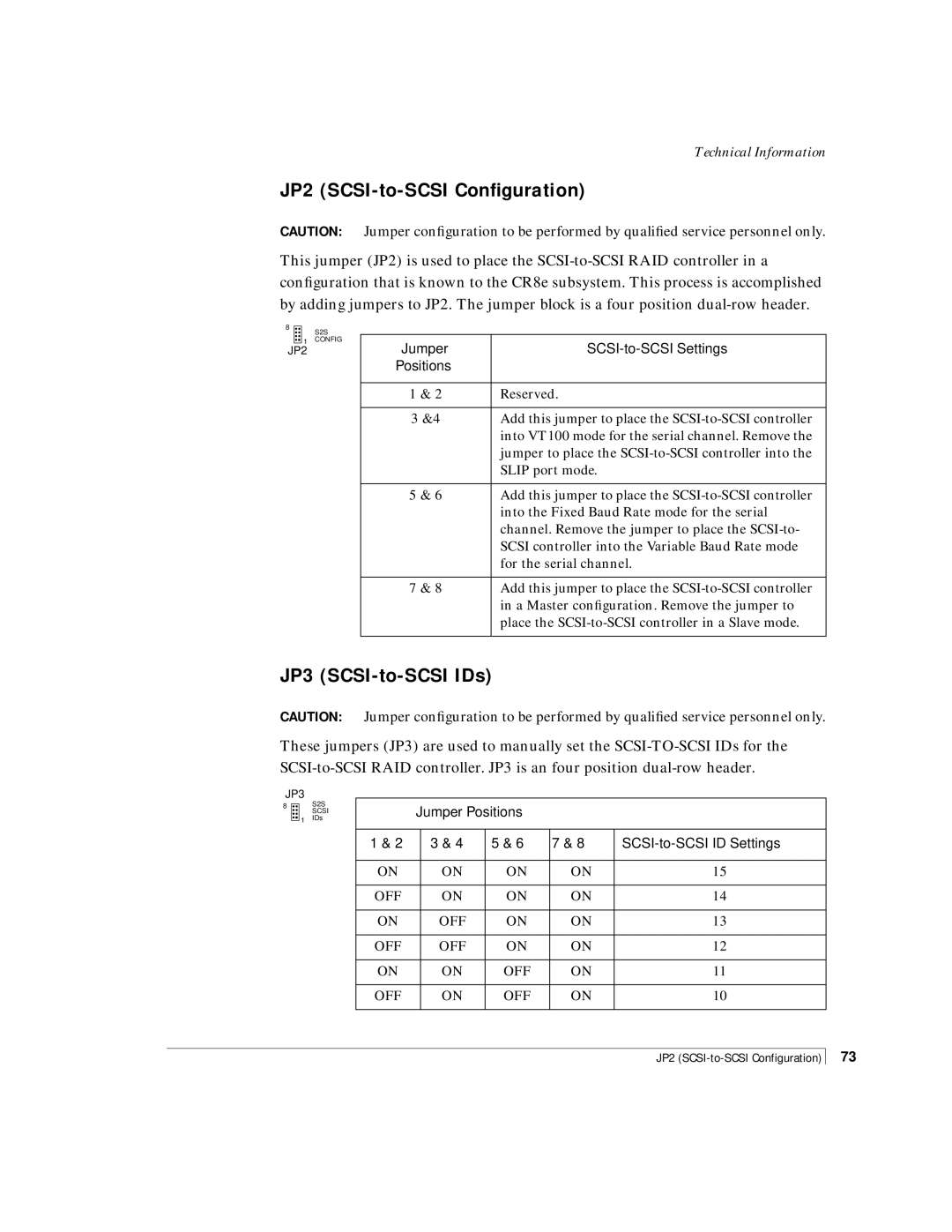
CR8e, Disk Array Enclosure specifications
NStor Technologies has long been recognized for its innovative storage solutions, and the CR8e Disk Array Enclosure is a prime example of this legacy. Designed to meet the growing demands of data storage in enterprise environments, the CR8e offers a robust and efficient platform for managing and securing critical data.One of the standout features of the CR8e is its impressive capacity. Supporting up to eight 3.5-inch or 2.5-inch drive bays, it allows for flexibility in choosing the right drives, including SATA, SAS, and SSD options. This adaptability not only meets varying performance requirements but also ensures that organizations can tailor their storage solutions based on specific operational needs.
The CR8e is designed with redundancy in mind, featuring hot-swappable drive bays that enable users to replace drives without downtime, thus ensuring continuous operation. Additionally, its dual-redundant power supplies and cooling fans provide enhanced reliability. This feature is crucial for businesses that cannot afford interruptions, ensuring that their data remains secure and accessible at all times.
In terms of connectivity, the NStor CR8e supports multiple interface options, including both SAS and SATA, catering to different storage protocols and enhancing compatibility with existing systems. It is equipped with advanced RAID functionalities, supporting various RAID levels such as 0, 1, 5, and 6. This capability allows users to choose the most suitable data protection and performance strategy for their environment.
Management is made simple thanks to its user-friendly interface, which offers ease of configuration and monitoring. The enclosure also provides comprehensive diagnostic and reporting features, assisting administrators in maintaining optimal storage conditions and prolonging the lifespan of the equipment.
Furthermore, the CR8e is designed with scalability in mind. As data storage needs grow, organizations can easily expand their storage capacity by adding more enclosures. This feature allows businesses to future-proof their investments in storage technology.
NStor Technologies has incorporated cutting-edge technologies in the CR8e to ensure high-speed data transfer rates, reducing latency and enhancing overall system performance. The enclosure’s design emphasizes thermal efficiency, ensuring that the internal components are kept at optimal temperatures even during high-performance operations.
In summary, the NStor Technologies CR8e Disk Array Enclosure is a versatile and powerful solution for organizations seeking to enhance their data storage capabilities. With its robust features, excellent scalability, and emphasis on reliability, it stands out as an ideal choice for enterprises focused on safeguarding their data assets.

