NVIDIA Frame Synchronization Under Windows XP
Set Up the Hardware
1.Daisy chain the graphics cards together using a standard CAT5 patch cable plugged into the external RJ45 connector.
You can connect to any of the two RJ45 connectors located on the graphics card bracket.
Each connector automatically configures itself as an input or output after all the connections are made and one system is configured as a synchronization server (see Set Up the Server Software on page 18). A flashing green LED indicates an input and a flashing yellow LED indicates an output.
If there is no server assigned and connected, then both LEDs are a steady green.
Note: WARNING! The voltage and signal on the frame lock ports are different from Ethernet signals. Do not connect a Frame lock port to an Ethernet card or network hub. Doing so can cause damage to the hardware.
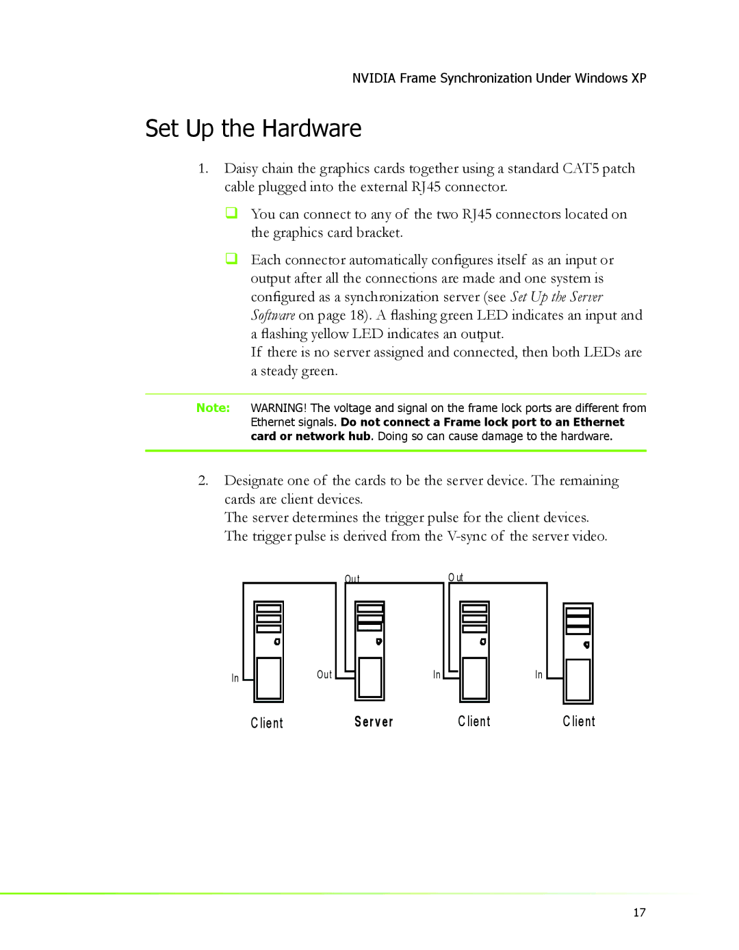
2.Designate one of the cards to be the server device. The remaining cards are client devices.
The server determines the trigger pulse for the client devices. The trigger pulse is derived from the
Ou t | O ut |
In | Ou t |
| In | In |
| C lient | S er ver | C lient | C lient |
17