Chapter 4 Software Development
Section
Section
Section
Sections
4-1. USB Basics
4-1-1. Bus Topology, Addresses, and Hot Plugging
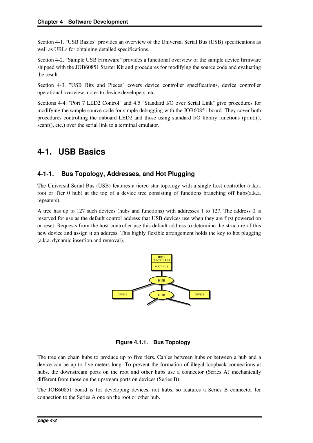
The Universal Serial Bus (USB) features a tiered star topology with a single host controller (a.k.a. root or Tier 0 hub) at the top of a device tree consisting of functions branching off hubs(a.k.a. repeaters).
A tree has up to 127 such devices (hubs and functions) with addresses 1 to 127. The address 0 is reserved for use as the default control address that USB devices use when they are first powered on or reset. Requests from the host controller use this default address to determine the structure of this new device and assign it an address. This highly flexible arrangement holds the key to hot plugging (a.k.a. dynamic insertion and removal).
HOST
HOST
CONTROLLER
CONTROLLER
ROOT HUB
ROOT HUB
HUB
HUB
DEVICE | HUB |
DEVICE | |
| HUB |
HUB
HUB
DEVICE |
DEVICE |
DEVICE |
DEVICE |
DEVICE |
DEVICE |
DEVICE |
DEVICE |
Figure 4.1.1. Bus Topology
The tree can chain hubs to produce up to five tiers. Cables between hubs or between a hub and a device can be up to five meters long. To prevent the formation of illegal loopback connections at hubs, the downstream ports on the root and other hubs use a connector (Series A) mechanically different from those on the upstream ports on devices (Series B).
The JOB60851 board is for developing devices, not hubs, so features a Series B connector for connection to the Series A one on the root or other hub.
page