Chapter 2 Putting Board through its Paces
2-1. Setup
2-1-1. Configuring JOB60851 Board
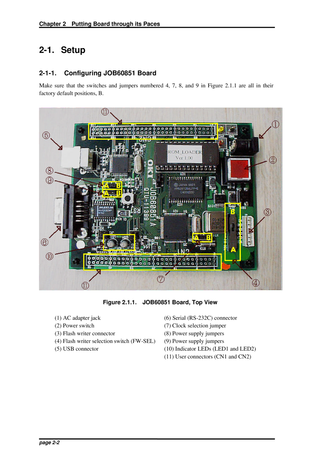
Make sure that the switches and jumpers numbered 4, 7, 8, and 9 in Figure 2.1.1 are all in their factory default positions, B.
| Figure 2.1.1. JOB60851 Board, Top View | |||
(1) | AC adapter jack | (6) | Serial | |
(2) | Power switch | (7) | Clock selection jumper | |
(3) | Flash writer connector | (8) | Power supply jumpers | |
(4) | Flash writer selection switch | (9) | Power supply jumpers | |
(5) | USB connector | (10) | Indicator LEDs (LED1 and LED2) | |
|
| (11) | User connectors (CN1 and CN2) | |
page