Chapter 3 System Specifications
3-3. System Limitations
3-3-1. Resources Uses
The user connectors (CN1 and CN2) on the JOB60851 board make available to the user application system almost all onboard MSM66Q573 microcontroller pins and thus most microcontroller functionality.
The JOB60851 board, however, monopolizes certain microcontroller resources in running its own system, making them unavailable to the developer.
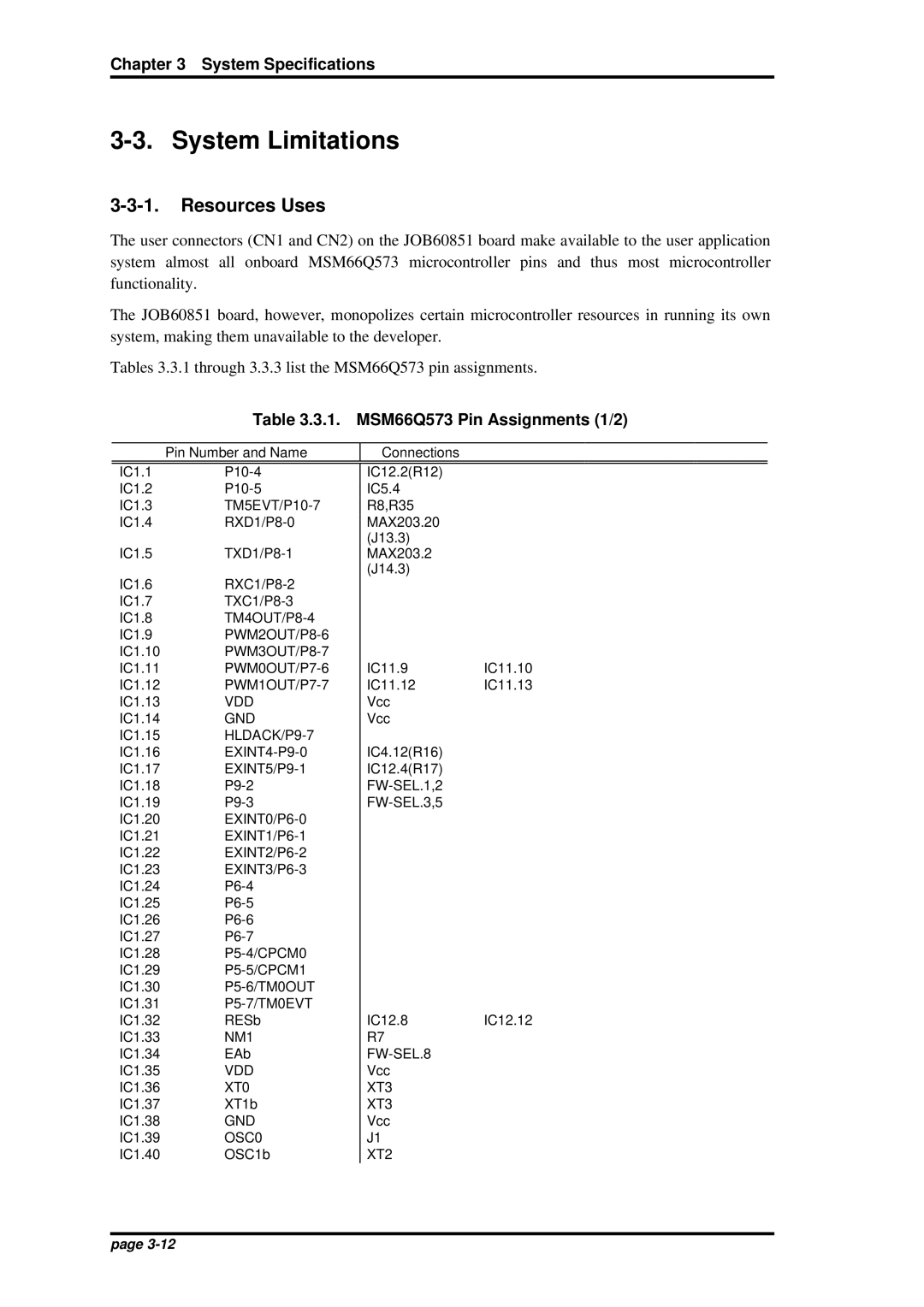
Tables 3.3.1 through 3.3.3 list the MSM66Q573 pin assignments.
Table 3.3.1. MSM66Q573 Pin Assignments (1/2)
Pin Number and Name
Connections
IC1.1 | |
IC1.2 | |
IC1.3 | |
IC1.4 | |
IC1.5 | |
IC1.6 | |
IC1.7 | |
IC1.8 | |
IC1.9 | |
IC1.10 | |
IC1.11 | |
IC1.12 | |
IC1.13 | VDD |
IC1.14 | GND |
IC1.15 | |
IC1.16 | |
IC1.17 | |
IC1.18 | |
IC1.19 | |
IC1.20 | |
IC1.21 | |
IC1.22 | |
IC1.23 |
|
IC1.24 | |
IC1.25 | |
IC1.26 | |
IC1.27 | |
IC1.28 | |
IC1.29 | |
IC1.30 | |
IC1.31 | |
IC1.32 | RESb |
IC1.33 | NM1 |
IC1.34 | EAb |
IC1.35 | VDD |
IC1.36 | XT0 |
IC1.37 | XT1b |
IC1.38 | GND |
IC1.39 | OSC0 |
IC1.40 | OSC1b |
IC12.2(R12)
IC5.4
R8,R35
MAX203.20
(J13.3)
MAX203.2
(J14.3)
IC11.9 IC11.10
IC11.12 IC11.13
Vcc
Vcc
IC4.12(R16)
IC12.4(R17)
IC12.8 IC12.12 R7
J1
XT2
page