Chapter 4 Software Development
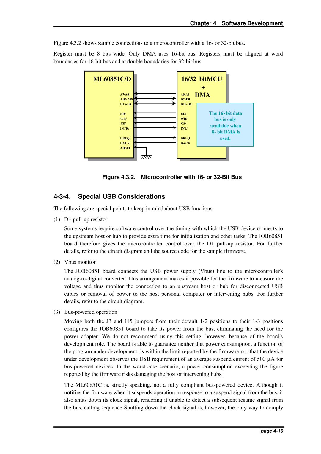
Figure 4.3.2 shows sample connections to a microcontroller with a 16- or 32-bit bus.
Register must be 8 bits wide. Only DMA uses 16-bit bus. Registers must be aligned at word boundaries for 16-bit bus and at double boundaries for 32-bit bus.
ML60851C/D
A7-A0
AD7-AD0
D15-D8
RD/
WR/
CS/
INTR/
DREQ
DACK
ADSEL
16/32 bitMCU
+
A8-A1 DMA
D7-D0
D15-D8
| RD/ | The 16- bit data |
| WR/ | bus is only |
| CS/ | available when |
| INT/ |
| 8- bit DMA is |
| |
| DREQ | used. |
| DACK | |
Figure 4.3.2. Microcontroller with 16- or 32-Bit Bus
4-3-4. Special USB Considerations
The following are special points to keep in mind about USB functions.
(1)D+ pull-up resistor
Some systems require software control over the timing with which the USB device connects to the upstream host or hub to provide extra time for initialization and other tasks. The JOB60851 board therefore gives the microcontroller control over the D+ pull-up resistor. For further details, refer to the circuit diagram and the source code for the sample firmware.
(2)Vbus monitor
The JOB60851 board connects the USB power supply (Vbus) line to the microcontroller's analog-to-digital converter. This arrangement makes it possible for the firmware to measure the voltage and thus monitor the connection to an upstream host or hub for disconnected USB cables or removal of power to the host personal computer or intervening hubs. For further details, refer to the circuit diagram.
(3)Bus-powered operation
Moving both the J3 and J15 jumpers from their default 1-2 positions to their 1-3 positions configures the JOB60851 board to take its power from the bus, eliminating the need for the power adapter. We do not recommend using this setting, however, because of the board's development role. The board is able to guarantee neither that power consumption, a function of the program under development, is within the limit reported by the firmware nor that the device under development observes the USB requirement of an average suspend current of 500 μA for bus-powered devices. In the worst case scenario, a power consumption exceeding the figure reported by the firmware risks damaging the host or intervening hubs.
The ML60851C is, strictly speaking, not a fully compliant bus-powered device. Although it notifies the firmware when it suspends operation in response to a suspend signal from the bus, it also shuts down its clock signal, rendering it unable to detect a subsequent resume signal from the bus. calling sequence Shutting down the clock signal is, however, the only way to comply