f)Using a 0-5VDC Input / Output Power Adapter Package.
An optional
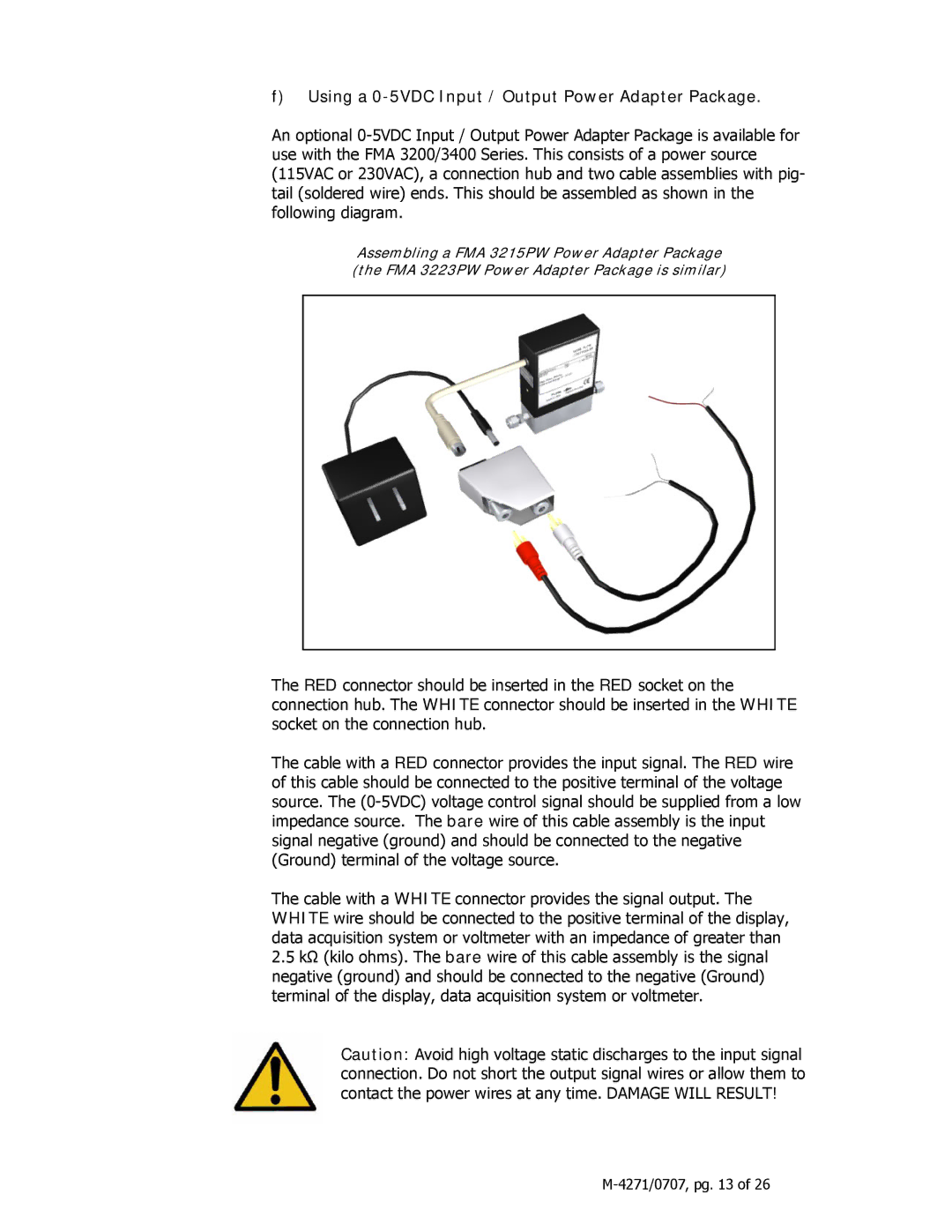
Assembling a FMA 3215PW Power Adapter Package (the FMA 3223PW Power Adapter Package is similar)
The RED connector should be inserted in the RED socket on the connection hub. The WHITE connector should be inserted in the WHITE socket on the connection hub.
The cable with a RED connector provides the input signal. The RED wire of this cable should be connected to the positive terminal of the voltage source. The
The cable with a WHITE connector provides the signal output. The WHITE wire should be connected to the positive terminal of the display, data acquisition system or voltmeter with an impedance of greater than
2.5kΩ (kilo ohms). The bare wire of this cable assembly is the signal negative (ground) and should be connected to the negative (Ground) terminal of the display, data acquisition system or voltmeter.
Caution: Avoid high voltage static discharges to the input signal connection. Do not short the output signal wires or allow them to contact the power wires at any time. DAMAGE WILL RESULT!