If a gas other than the calibration gas is used then the adjusted maximum (full scale) flow for the unit should be calculated using the K Factor for that gas (see section C3 above).
A zero or negative set-point voltage will cause the solenoid valve to close fully. Whilst closed, the valve is configured to withstand pressures up to 60 psig (higher pressures on request).
Caution: The flow controller valve will open if the pressure exceeds 60psig. For safety it is recommended that a separate positive shut-off valve is installed upstream of the controller.
5.Changing The Flow Rate Set-Point – FMA3400/3400ST Series Only
On the FMA 3400/3400ST Series the set-point may be input from an external source or be supplied internally.
For an external set-point, dip switch 1 should be OFF and dip switch 2 ON. See section C4 above for details of how to adjust the set-point using an external voltage source.
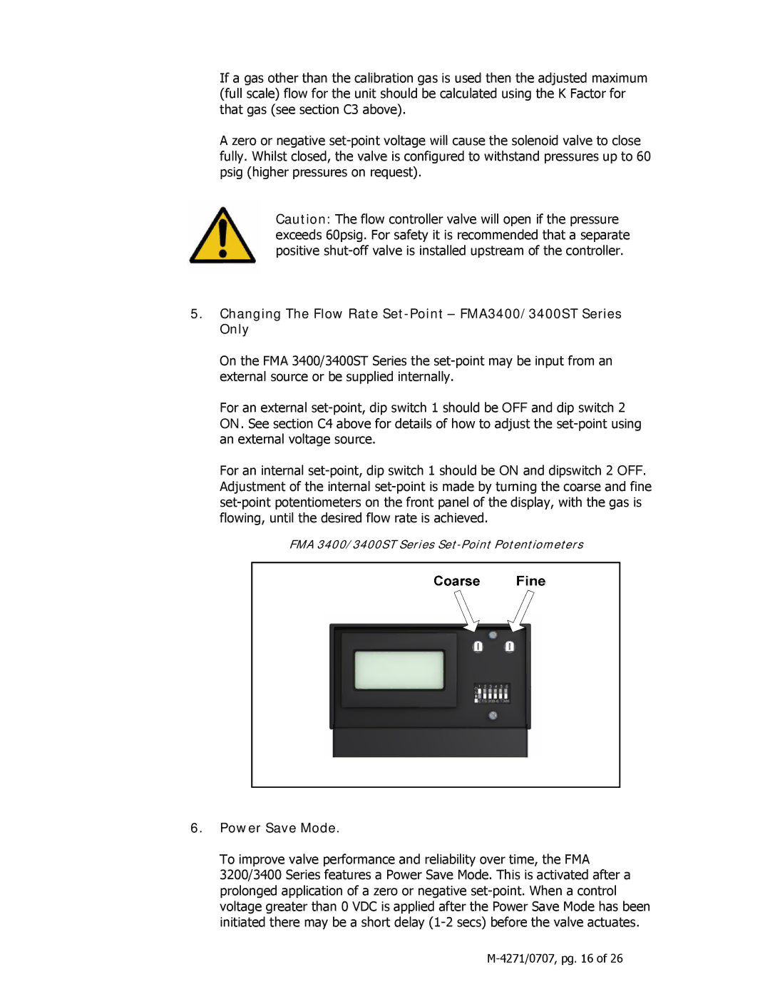
For an internal set-point, dip switch 1 should be ON and dipswitch 2 OFF. Adjustment of the internal set-point is made by turning the coarse and fine set-point potentiometers on the front panel of the display, with the gas is flowing, until the desired flow rate is achieved.
FMA 3400/3400ST Series Set-Point Potentiometers
6.Power Save Mode.
To improve valve performance and reliability over time, the FMA 3200/3400 Series features a Power Save Mode. This is activated after a prolonged application of a zero or negative set-point. When a control voltage greater than 0 VDC is applied after the Power Save Mode has been initiated there may be a short delay (1-2 secs) before the valve actuates.
M-4271/0707, pg. 16 of 26