e)Connections For The 15 D Sub Connector
Using a suitable mating connector the pins of the integrated connector should be wired as follows:
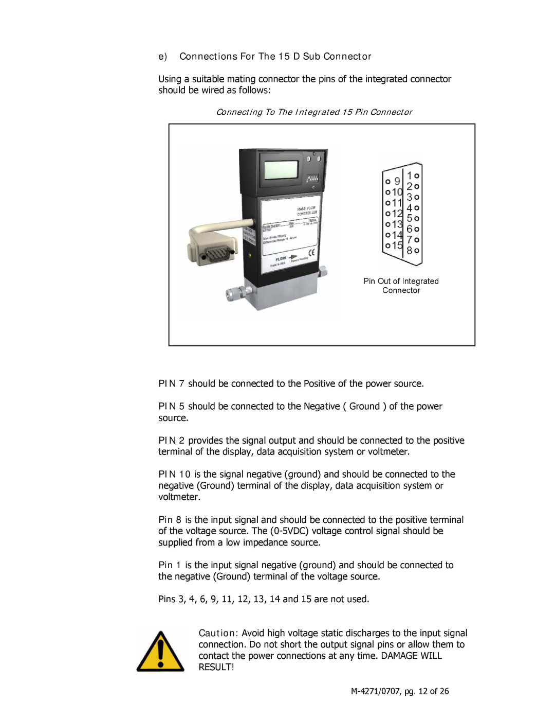
Connecting To The Integrated 15 Pin Connector
Pin Out of Integrated
Connector
PIN 7 should be connected to the Positive of the power source.
PIN 5 should be connected to the Negative ( Ground ) of the power source.
PIN 2 provides the signal output and should be connected to the positive terminal of the display, data acquisition system or voltmeter.
PIN 10 is the signal negative (ground) and should be connected to the negative (Ground) terminal of the display, data acquisition system or voltmeter.
Pin 8 is the input signal and should be connected to the positive terminal of the voltage source. The
Pin 1 is the input signal negative (ground) and should be connected to the negative (Ground) terminal of the voltage source.
Pins 3, 4, 6, 9, 11, 12, 13, 14 and 15 are not used.
Caution: Avoid high voltage static discharges to the input signal connection. Do not short the output signal pins or allow them to contact the power connections at any time. DAMAGE WILL RESULT!