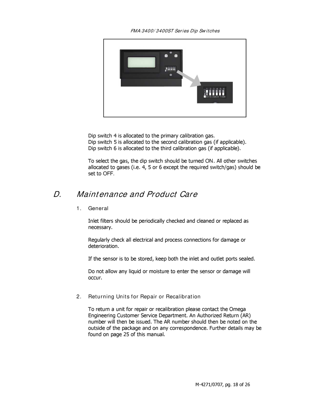
FMA 3400/3400ST Series Dip Switches
Dip switch 4 is allocated to the primary calibration gas.
Dip switch 5 is allocated to the second calibration gas (if applicable). Dip switch 6 is allocated to the third calibration gas (if applicable).
To select the gas, the dip switch should be turned ON. All other switches allocated to gases (i.e. 4, 5 or 6 except the required switch/gas) should be set to OFF.
D.Maintenance and Product Care
1.General
Inlet filters should be periodically checked and cleaned or replaced as necessary.
Regularly check all electrical and process connections for damage or deterioration.
If the sensor is to be stored, keep both the inlet and outlet ports sealed.
Do not allow any liquid or moisture to enter the sensor or damage will occur.
2.Returning Units for Repair or Recalibration
To return a unit for repair or recalibration please contact the Omega Engineering Customer Service Department. An Authorized Return (AR) number will then be issued. The AR number should then be noted on the outside of the package and on any correspondence. Further details may be found on page 25 of this manual.