2.6 BACK OF THE METER
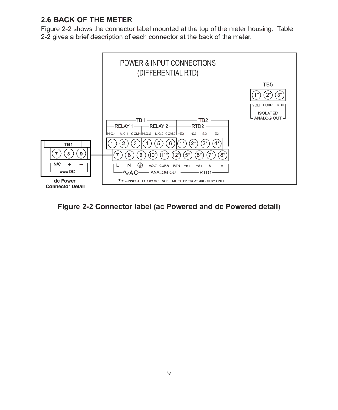
Figure 2-2 shows the connector label mounted at the top of the meter housing. Table 2-2 gives a brief description of each connector at the back of the meter.
POWER & INPUT CONNECTIONS | |||
(DIFFERENTIAL RTD) |
|
| |
| RTD2 |
|
|
+E2 | +S2 |
| |
+E1 | +S1 | ||
| RTD1 |
| |
Figure 2-2 Connector label (ac Powered and dc Powered detail)
9