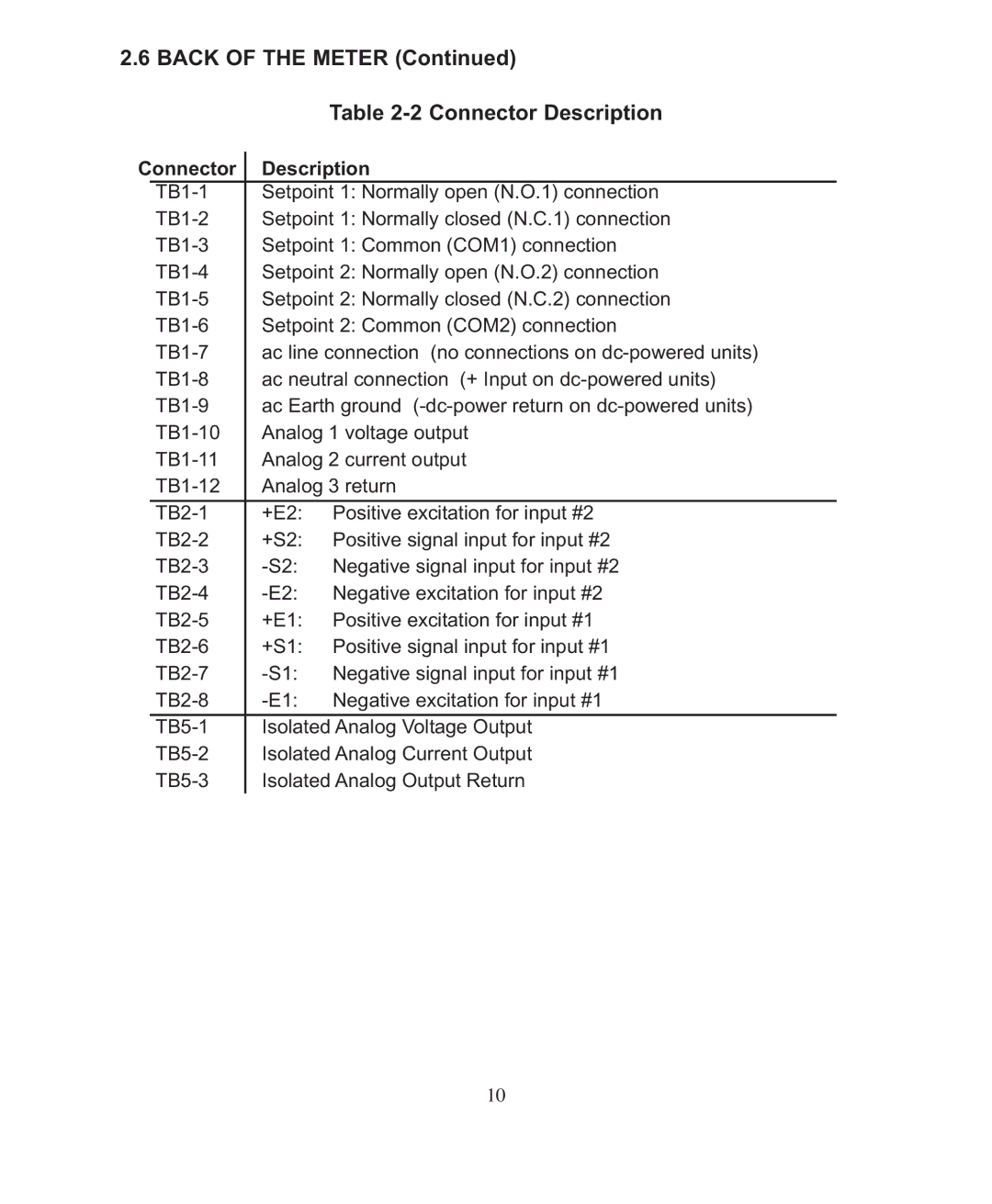
2.6 BACK OF THE METER (Continued)
|
|
|
| Table |
Connector |
| Description | ||
| ||||
|
| Setpoint 1: Normally open (N.O.1) connection | ||
|
| Setpoint 1: Normally closed (N.C.1) connection | ||
|
| Setpoint 1: Common (COM1) connection | ||
|
| Setpoint 2: Normally open (N.O.2) connection | ||
|
| Setpoint 2: Normally closed (N.C.2) connection | ||
|
| Setpoint 2: Common (COM2) connection | ||
|
| ac line connection (no connections on | ||
|
| ac neutral connection (+ Input on | ||
|
| ac Earth ground | ||
|
| Analog 1 voltage output | ||
|
| Analog 2 current output | ||
|
| Analog 3 return | ||
|
|
|
|
|
|
| +E2: | Positive excitation for input #2 | |
|
| +S2: | Positive signal input for input #2 | |
|
| Negative signal input for input #2 | ||
|
| Negative excitation for input #2 | ||
|
| +E1: | Positive excitation for input #1 | |
|
| +S1: | Positive signal input for input #1 | |
|
| Negative signal input for input #1 | ||
|
| Negative excitation for input #1 | ||
|
|
|
| |
|
| Isolated Analog Voltage Output | ||
|
| Isolated Analog Current Output | ||
|
| Isolated Analog Output Return | ||
|
|
|
|
|
10