3.4 CONNECTING SENSOR INPUT
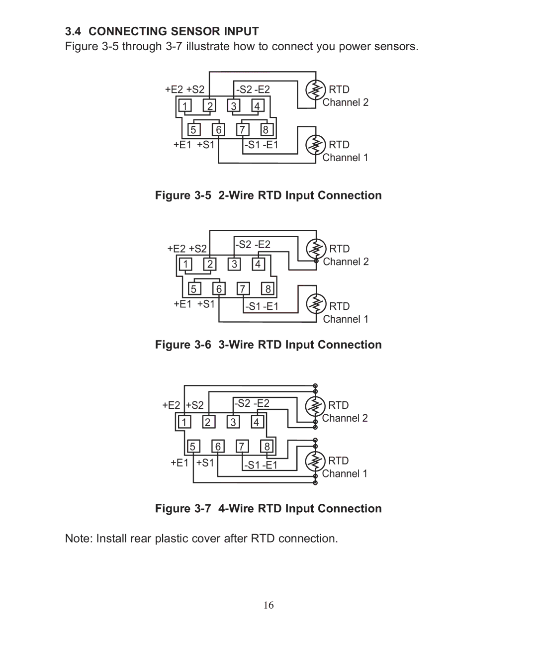
Figure 3-5 through 3-7 illustrate how to connect you power sensors.
+E2 +S2 |
| RTD | ||
1 | 2 | 3 | 4 | Channel 2 |
| ||||
5 | 6 | 7 | 8 |
|
+E1 +S1 | RTD | |||
|
|
|
| Channel 1 |
Figure 3-5 2-Wire RTD Input Connection
+E2 +S2 |
| RTD | ||
|
|
| ||
1 | 2 | 3 | 4 | Channel 2 |
5 | 6 | 7 | 8 |
|
+E1 +S1 |
| RTD | ||
|
|
|
| Channel 1 |
Figure 3-6 3-Wire RTD Input Connection
+E2 +S2 | RTD | |||
1 | 2 | 3 | 4 | Channel 2 |
| ||||
5 | 6 | 7 | 8 |
|
+E1 | +S1 |
| RTD | |
|
|
|
| Channel 1 |
Figure 3-7 4-Wire RTD Input Connection
Note: Install rear plastic cover after RTD connection.
16