3.3 MOUNTING THE METER
PANEL
|
| REAR |
|
|
| (REMOVED) | |
| CONNECTOR |
| COVER |
|
|
| |
| LABEL |
|
|
PRODUCT |
| CASE | |
LABEL |
| ||
"NEW" STYLE MOUNTING BRACKET
"OLDER" STYLE MOUNTING BRACKET 2 PCS
GASKET
FRONT BEZEL
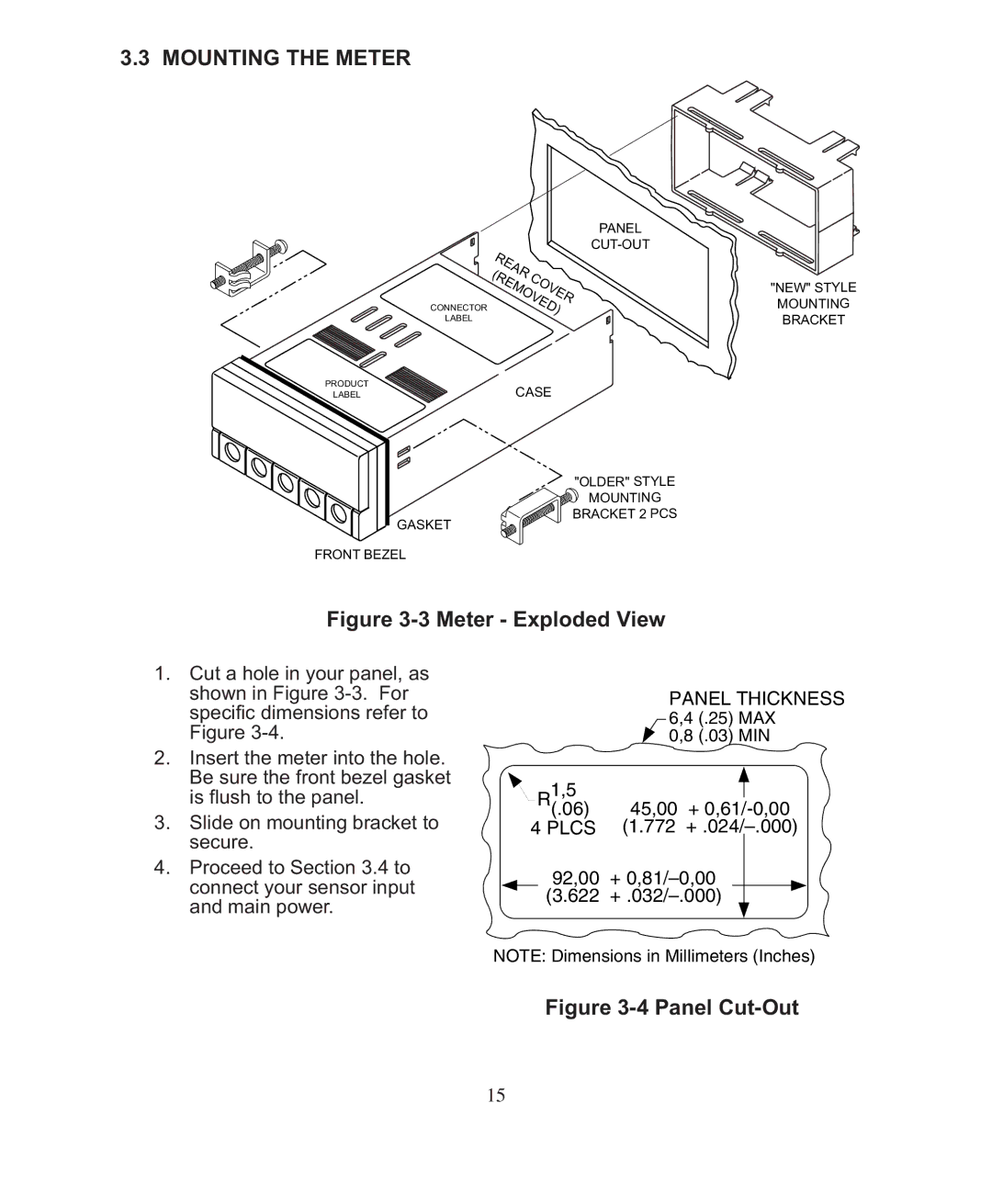
Figure 3-3 Meter - Exploded View
1.Cut a hole in your panel, as shown in Figure
2.Insert the meter into the hole. Be sure the front bezel gasket is flush to the panel.
3.Slide on mounting bracket to secure.
PANEL THICKNESS
| 6,4 (.25) | MAX | |
| 0,8 (.03) | MIN | |
1,5 |
|
|
|
R(.06) | 45,00 | + | |
4 PLCS | (1.772 | ||
4. Proceed to Section 3.4 to | 92,00 | + | |
connect your sensor input | |||
(3.622 | |||
and main power. | |||
|
|
NOTE: Dimensions in Millimeters (Inches)
Figure 3-4 Panel Cut-Out
15