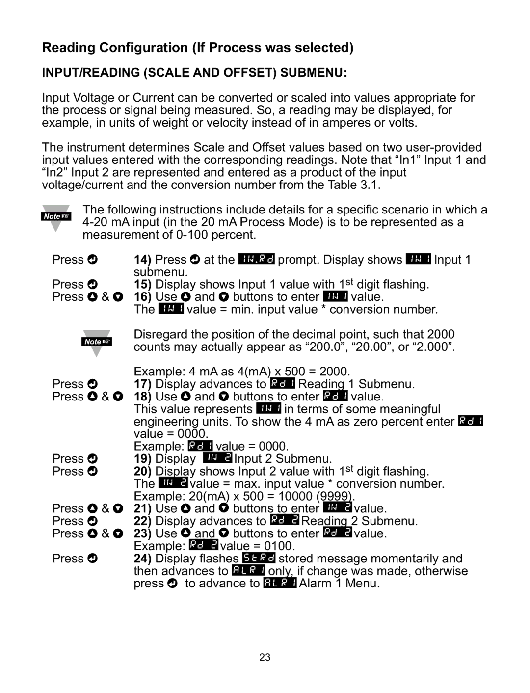
ILD24-UTP, ILD44-UTP specifications
The Omega ILD44-UTP and ILD24-UTP are advanced intrusion detection sensors designed for versatile security applications. These devices stand out due to their cutting-edge technology, ensuring reliability and high performance in safeguarding various environments.One of the primary features of the ILD44-UTP and ILD24-UTP is their unique dual-tech detection capability. By utilizing both passive infrared (PIR) and microwave detection, these sensors significantly reduce false alarms while ensuring accurate intrusion detection. The combination of these technologies allows for effective monitoring in different settings, including residential, commercial, and industrial spaces.
The ILD44-UTP model is equipped with a wider detection range compared to its counterpart, the ILD24-UTP. It is capable of covering a detection area of up to 44 meters, making it ideal for larger spaces. Conversely, the ILD24-UTP provides effective coverage for smaller areas, reaching up to 24 meters. This range flexibility gives users the option to select a model that best fits their particular needs.
Another important characteristic is the sensor's weather-resistant design, which allows it to be installed outdoors without compromising performance. The ILD44-UTP and ILD24-UTP are rated for various environmental conditions, ensuring they remain operational in rain, snow, or extreme temperatures. This durability makes them suitable for use on building perimeters, parking lots, and other outdoor security applications.
Both models are equipped with advanced signal processing algorithms that enhance their ability to differentiate between real threats and environmental disturbances, greatly minimizing false alarm rates. This feature is especially critical in settings where frequent alarms can lead to alarm fatigue among security personnel.
The installation process for both devices is straightforward, with user-friendly mounting options. They can be easily integrated into existing security systems, offering flexibility for users to combine them with other security measures such as cameras and access control systems.
Additionally, the ILD44-UTP and ILD24-UTP come with various output options, including relay and voltage outputs, enabling seamless integration with alarm systems and monitoring solutions. Their compatibility with different protocols ensures they can be tied into a wide array of security infrastructures.
Overall, the Omega ILD44-UTP and ILD24-UTP sensors represent a significant advancement in intrusion detection technology, combining robust performance with innovative features that cater to a variety of security needs. Their versatility, durability, and reliability position them as top choices for enhancing security across numerous applications.

