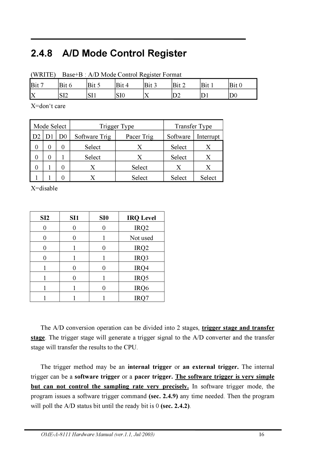
2.4.8A/D Mode Control Register
(WRITE) |
| Base+B : A/D Mode Control Register Format |
|
|
|
|
| ||||||||||||
Bit 7 | Bit 6 |
| Bit 5 | Bit 4 |
| Bit 3 |
| Bit 2 |
| Bit 1 | Bit 0 | ||||||||
X |
|
| SI2 |
| SI1 | SI0 |
| X |
| D2 |
| D1 | D0 | ||||||
X=don‘t care |
|
|
|
|
|
|
|
|
|
|
|
|
|
| |||||
|
|
|
|
|
|
|
|
|
|
|
|
|
|
|
| ||||
Mode Select |
|
|
| Trigger Type |
| Transfer Type |
|
| |||||||||||
D2 | D1 |
| D0 | Software Trig |
| Pacer Trig | Software | Interrupt |
|
| |||||||||
0 | 0 |
| 0 |
| Select |
|
| X | Select |
| X |
|
|
| |||||
0 | 0 |
| 1 |
| Select |
|
| X | Select |
| X |
|
|
| |||||
0 | 1 |
| 0 |
|
|
| X |
|
| Select |
| X |
| X |
|
|
| ||
1 | 1 |
| 0 |
|
|
| X |
|
| Select | Select |
| Select |
|
|
| |||
X=disable |
|
|
|
|
|
|
|
|
|
|
|
|
|
|
|
|
| ||
|
|
|
|
|
|
|
|
|
|
|
|
|
|
| |||||
SI2 |
| SI1 |
|
| SI0 |
| IRQ Level |
|
|
|
|
|
|
| |||||
| 0 |
|
| 0 |
| 0 |
|
| IRQ2 |
|
|
|
|
|
|
| |||
| 0 |
|
| 0 |
| 1 |
|
| Not used |
|
|
|
|
|
|
| |||
| 0 |
|
| 1 |
| 0 |
|
| IRQ2 |
|
|
|
|
|
|
| |||
| 0 |
|
| 1 |
| 1 |
|
| IRQ3 |
|
|
|
|
|
|
| |||
| 1 |
|
| 0 |
| 0 |
|
| IRQ4 |
|
|
|
|
|
|
| |||
| 1 |
|
| 0 |
| 1 |
|
| IRQ5 |
|
|
|
|
|
|
| |||
| 1 |
|
| 1 |
| 0 |
|
| IRQ6 |
|
|
|
|
|
|
| |||
| 1 |
|
| 1 |
| 1 |
|
| IRQ7 |
|
|
|
|
|
|
| |||
The A/D conversion operation can be divided into 2 stages, trigger stage and transfer stage. The trigger stage will generate a trigger signal to the A/D converter and the transfer stage will transfer the results to the CPU.
The trigger method may be an internal trigger or an external trigger. The internal trigger can be a software trigger or a pacer trigger. The software trigger is very simple but can not control the sampling rate very precisely. In software trigger mode, the program issues a software trigger command (sec. 2.4.9) any time needed. Then the program will poll the A/D status bit until the ready bit is 0 (sec. 2.4.2).
16 |