The pacer trigger can control the sampling rate very precisely. So the converted data can be used to reconstruct the waveform of the analog input signal. In pacer trigger mode, the pacer timer will periodically generate trigger signals to the A/D converter. This converted data can be transfer to the CPU by polling or interrupt or DMA transfer method.
The software driver provides three polling or
2.4.9A/D Software Trigger Control Register
(WRITE) | Base+C : A/D Software Trigger Control Register Format |
| |||||
Bit 7 | Bit 6 | Bit 5 | Bit 4 | Bit 3 | Bit 2 | Bit 1 | Bit 0 |
X | X | X | X | X | X | X | X |
X=don‘t care, XXXXXXXX=any 8 bits data is validate
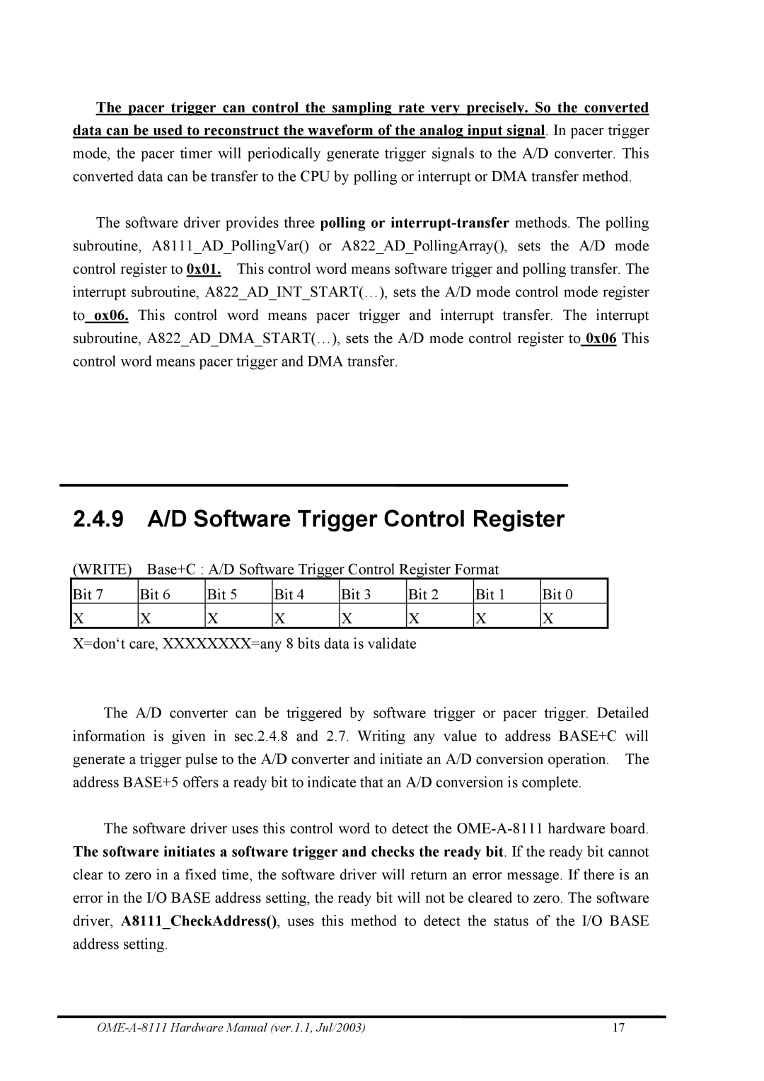
The A/D converter can be triggered by software trigger or pacer trigger. Detailed information is given in sec.2.4.8 and 2.7. Writing any value to address BASE+C will generate a trigger pulse to the A/D converter and initiate an A/D conversion operation. The address BASE+5 offers a ready bit to indicate that an A/D conversion is complete.
The software driver uses this control word to detect the
17 |
