2.7 A/D Conversion
This section explains how to perform A/D conversions. The A/D conversion can be performed by software trigger by pacer trigger. At the end of the A/D conversion, it is possible to transfer data by polling and interrupt before using the A/D conversion function; users should notice the following issues:
zA/D data register, BASE+4/BASE+5, stores the A/D conversion data
z A/D gain control register, BASE+9, select gain (sec. 2.4.6)
zA/D multiplex control register, BASE+A, select analog input
zA/D mode control register, BASE+B, select trigger type and transfer type (sec. 2.4.8)
z A/D software trigger control register, BASE+C (sec. 2.4.9)
(sec. 2.4.2)
(sec. 2.4.7)
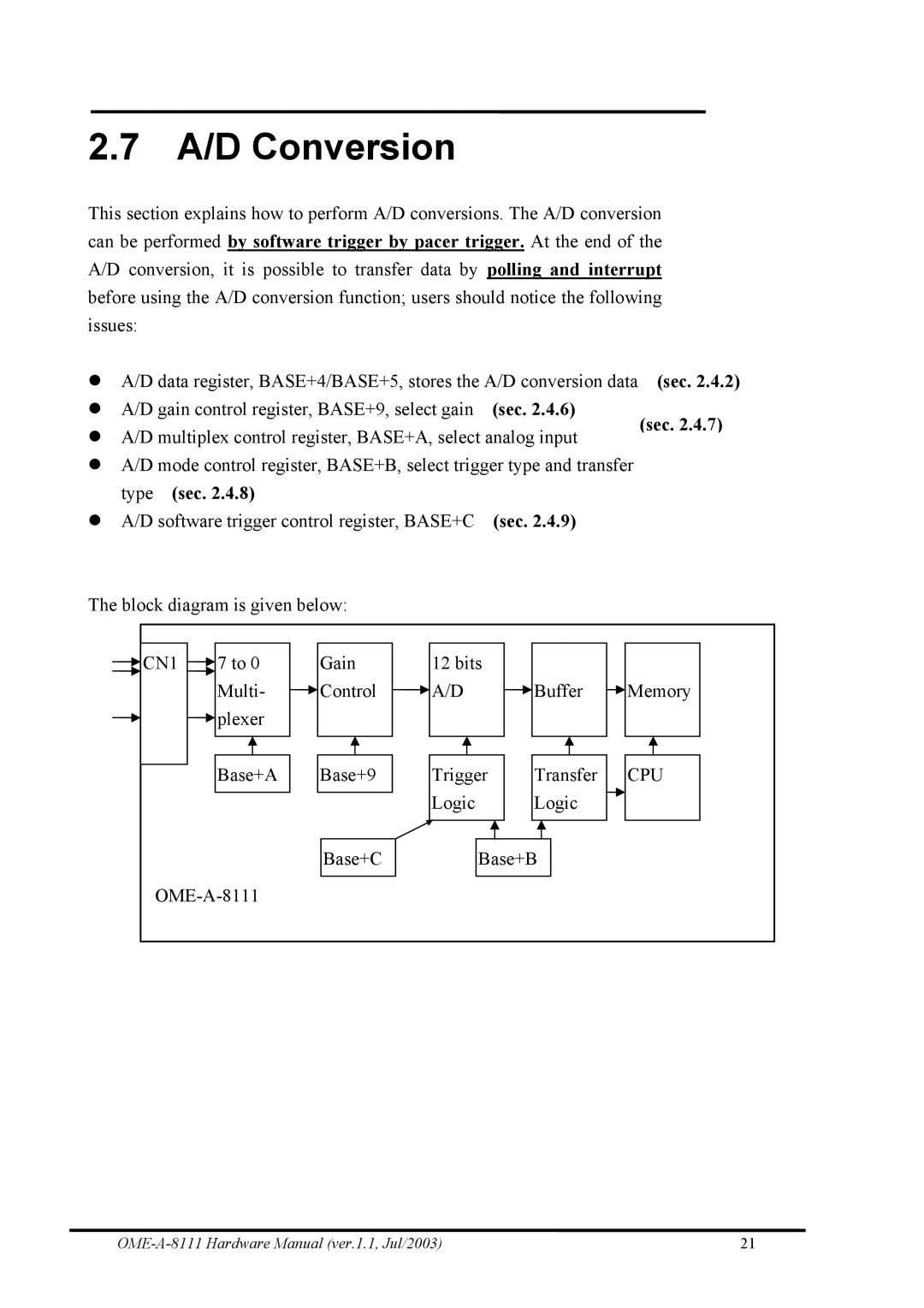
The block diagram is given below:
CN1 | 7 to 0 | Gain | 12 bits |
|
|
| Multi- | Control | A/D | Buffer | Memory |
| plexer |
|
|
|
|
| Base+A | Base+9 | Trigger | Transfer | CPU |
|
|
| Logic | Logic |
|
|
| Base+C | Base+B |
| |
|
|
|
| ||
21 |