2.68254 Timer/Counter
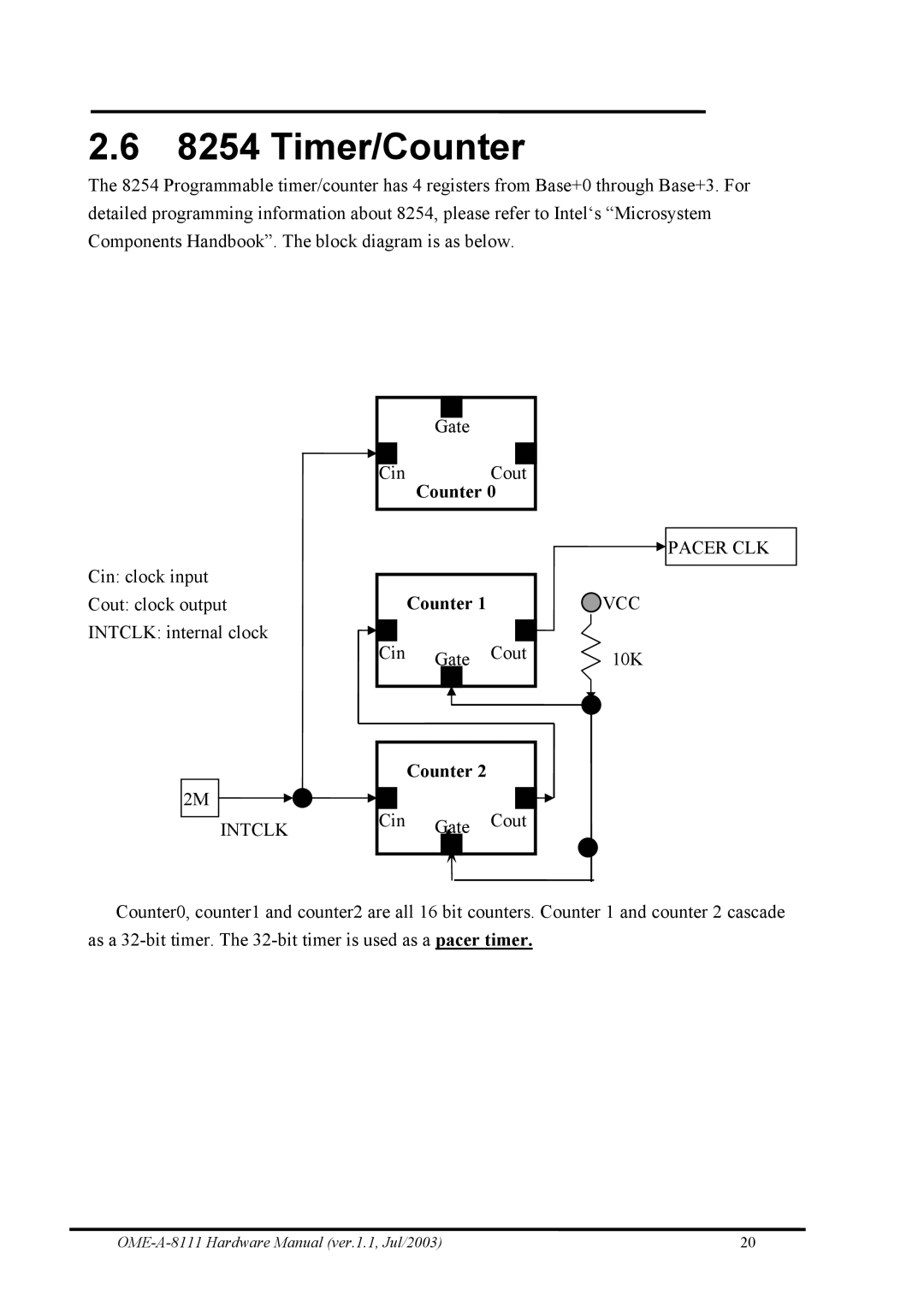
The 8254 Programmable timer/counter has 4 registers from Base+0 through Base+3. For detailed programming information about 8254, please refer to Intel‘s “Microsystem Components Handbook”. The block diagram is as below.
Gate |
Cin | Cout |
| Counter 0 |
Cin: clock input |
|
|
|
|
|
|
|
|
| Counter 1 |
|
| |||
Cout: clock output |
|
|
| ||||
INTCLK: internal clock |
|
|
|
|
|
|
|
|
|
|
|
|
|
| |
| Cin | Gate | Cout | ||||
|
|
|
|
|
|
|
|
|
| Counter 2 |
| |
2M | Cin |
| Cout | |
INTCLK | Gate | |||
|
|
 PACER CLK
 VCC
VCC
10K
Counter0, counter1 and counter2 are all 16 bit counters. Counter 1 and counter 2 cascade as a
20 |