HT-S5100
Avis
Important Safety Instructions
FCC Information for User
Precautions
Power
Using Close to a TV or Computer
Speaker Precautions
Precautions
Placement
Package Contents
Package Contents
Subwoofer
Indicator Output
Center speaker
Dock DS-A1L
Features
AV Receiver HT-R560
Features
Contents
Contents
Front Panel
Getting to Know the AV Receiver
Display
Getting to Know the AV Receiver
Rear Panel
Subwoofer PRE OUT
Front Rear
STANDBY/ON indicator
Speaker Package
Subwoofer SKW-560
SKF-560F SKM-560S/SKB-560 SKC-560C
Speaker Package
Keyhole slots
Speaker terminals
Controlling the AV Receiver
Remote Controller
Controlling a Dock DS-A1L
Remote Controller
Using the Remote Controller
Installing the Batteries
Enjoying Home Theater
Connecting Your Speakers
Speaker Configuration
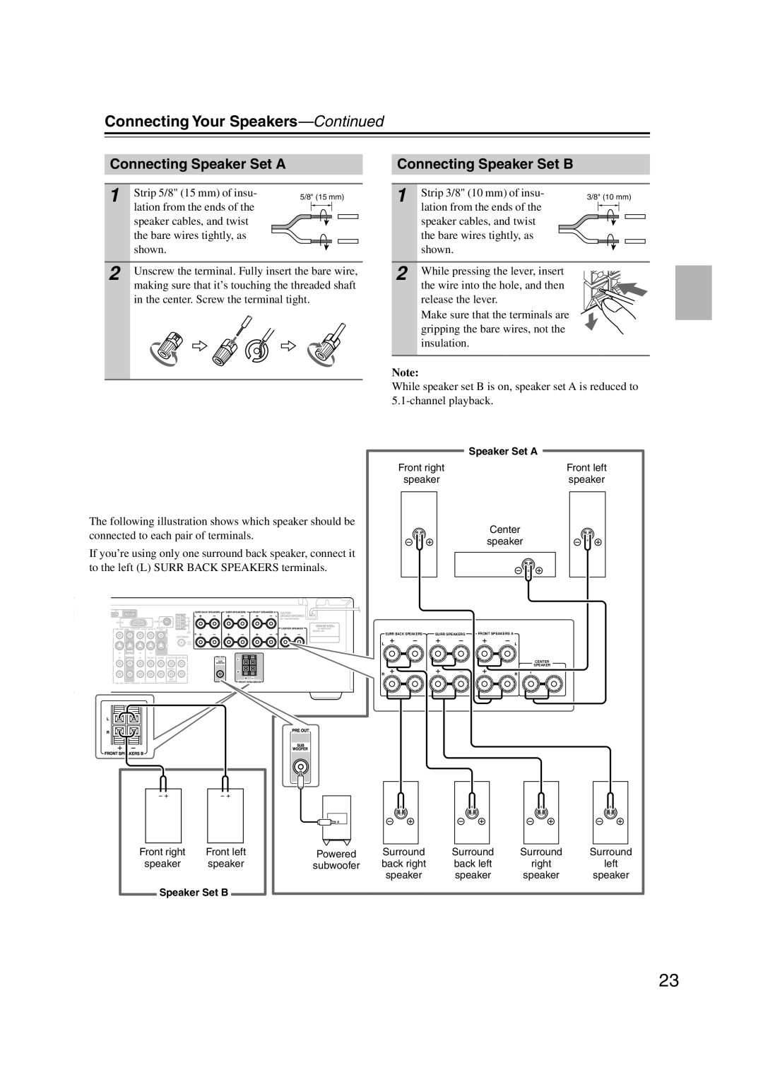
Connecting Your Speakers
Speaker Connection Precautions
Speaker Set B
Connecting Speaker Set a
Connecting Speaker Set B
Speaker Set a
Surround speaker/ Surround back speaker SKM-560S/SKB-560
Using the Floor Pads for Subwoofer
Wall Mounting
Front speaker SKF-560F
Attach the FM antenna, as shown American Model
Connecting Antennas
Connecting the AM Loop Antenna
Connecting the Indoor FM Antenna
Using a TV/FM Antenna Splitter
Connecting Antennas
Connecting an Outdoor FM Antenna
Connecting an Outdoor AM Antenna
AV Connection Color Coding
Connecting Your Components
About AV Connections
Optical Digital Jacks
Video Connection Formats
Connecting Your Components
Connecting Audio and Video Signals to the AV Receiver
Which Connections Should I Use?
Hint
Connecting a TV or Projector
Video Connection
Audio Connection
DVD player
Connecting a DVD player
Digital Component Video
Hooking Up the Multichannel Input
VCR or DVR
Connecting a VCR or DVR for Playback
Make the audio connection a
Connecting a VCR or DVR for Recording
CBL/SAT in S
HT-R560 Pass-thru
Connecting Components with Hdmi
About Hdmi
About Copyright Protection
DVD player Step
Audio Signals
Making Hdmi Connections
Tip
Camcorder, game console, etc
Connecting a Camcorder, Game Console, or Other Device
Connecting the Supplied DS-A1L Dock
Make the video connection a Make the audio connection a
Phono preamp
Step
CD player
CD or turntable
Coaxial CBL/SAT Optical
Connecting a Cassette, CDR, MiniDisc, or DAT Recorder
Remote Control
Connecting Onkyo Components
Connecting the Power Cord
Auto Power On/Standby
Up and Running in a Few Easy Steps
Do the automatic speaker setup-this is essential
Turning On the AV Receiver
Turning On and Standby
Measurement Positions
First Time Setup
Automatic Speaker Setup Audyssey 2EQ
Using Audyssey 2EQ
Changing the Speaker Settings Manually
First Time Setup
Error Messages
To Retry the Automatic Speaker Setup
Using a Powered Subwoofer
Hdmi Input Setup
Component Video Input Setup
Changing the Input Display
Digital Input Setup
Basic AV Receiver Operation
Select a listening mode and enjoy
See Using the Listening Modes on
Playing Your AV Components
Muting the AV Receiver
Setting the Display Brightness
Using the Sleep Timer
Common Functions
Interpreting Surround Channel Information
7Using Headphones
Common Functions
Displaying Source Information
Seconds
Specifying the Digital Signal Format
Press and hold the AV receiver’s
Digital Input button for about
Buttons to select 0.Hardware
AM Frequency Step Setup on some models
Listening to the Radio
Listening to AM/FM Stations
Tuning into AM/FM Radio Stations
Listening to the Radio
Band Frequency
Tuning into Stations by Frequency
Displaying AM/FM Radio Information
Tuner Display
Deleting Presets
Presetting AM/FM Stations
Selecting Presets
Positioning the Antenna
Setting Up the SiriusConnect Home Tuner
What is Sirius Satellite Radio?
Listening to Sirius Satellite Radio
Signing Up for Sirius Satellite Radio
Setting the Satellite Radio Mode
Listening to Sirius Satellite Radio
Selecting Sirius Satellite Radio
Selecting Sirius Satellite Radio Channels
Channel Search Mode
Category Search Mode
Direct Tuning
Displaying Sirius Satellite Radio Information
Presetting Sirius Channels
Positioning the SiriusConnect Home Tuner
Parental Lock
Changing the PIN Number
RDS Program Types PTY
Using RDS European models only
What is RDS?
Finding Stations by Type PTY
Displaying Radio Text RT
Listening to Traffic News TP
Putting Your iPod in the Dock
DS-A1L Dock for the iPod
About the DS-A1L Dock
Compatible iPod models
Operating Notes
Using Your iPod’s Alarm Clock
Charging Your iPod’s Battery
DS-A1L Dock for the iPod
Selecting on the AV Receiver
Using the Listening Modes
Selecting with the Remote Controller
Selecting the Listening Modes
Analog and PCM Sources
Using the Listening Modes
Listening Modes Available for Each Source Format
MOVIE/T
Dolby Digital Sources
DTS
DTS Sources
DTS
About the Listening Modes
Onkyo Original DSP Modes
Recording from Different AV Sources
Recording
Recording the Input Source
PLIIx/Neo6 Settings
Adjusting the Listening Modes
Using the Audio Adjust Settings
Multiplex/Mono Settings
Using the Audio Settings
Adjusting the Listening Modes
Music Optimizer
Late Night Function
CinemaFILTER
Audyssey Dynamic EQ
Speaker Setup
Advanced Setup
Left and Right Buttons to Select 2ch or 1ch
Advanced Setup
Crossover Frequency
Use the Down Button to
Speaker Distance
Double Bass
Repeat so that the level
Turn up the volume so that you
Can hear the test tone suffi
Ciently
Then use the Left and Right
Equalizer Settings
Then press Enter Use the Left and Right Buttons to select
Press the Down button,
Controlling Other Components
Preprogrammed Remote Control Codes
Entering Remote Control Codes
Controlling Other Components
Resetting the Remote Controller
Remote Control Codes for Onkyo Components Connected via
Resetting the Remote Mode Buttons
Controlling a DVD Player, or DVD Recorder
Prev CH button
Controlling a VCR, or PVR
CLR button
Guide button
Press the appropriate
Controlling a Satellite Receiver or Cable Receiver
Search button
Disc +/- button
Controlling a CD Player, CD Recorder, or MD Player
Reverse Play button
Controlling a Cassette Recorder
Previous and Next / buttons
Rewind and Fast Forward / buttons
TV VOL
Press TV Remote Mode button first
Controlling a TV
ON/STANDBY, TV buttons
Troubleshooting
Troubleshooting
Can’t record
Remote controller doesn’t work
Sound changes when I connect my head- phones
Can’t control other components
Tuner Section
Specifications
Amplifier Section
Video Section
1ch Home Theater Speaker Package
Specifications
Memo
Onkyo China Limited
Onkyo U.S.A. Corporation
Onkyo Europe Electronics GmbH
Onkyo Europe UK Office