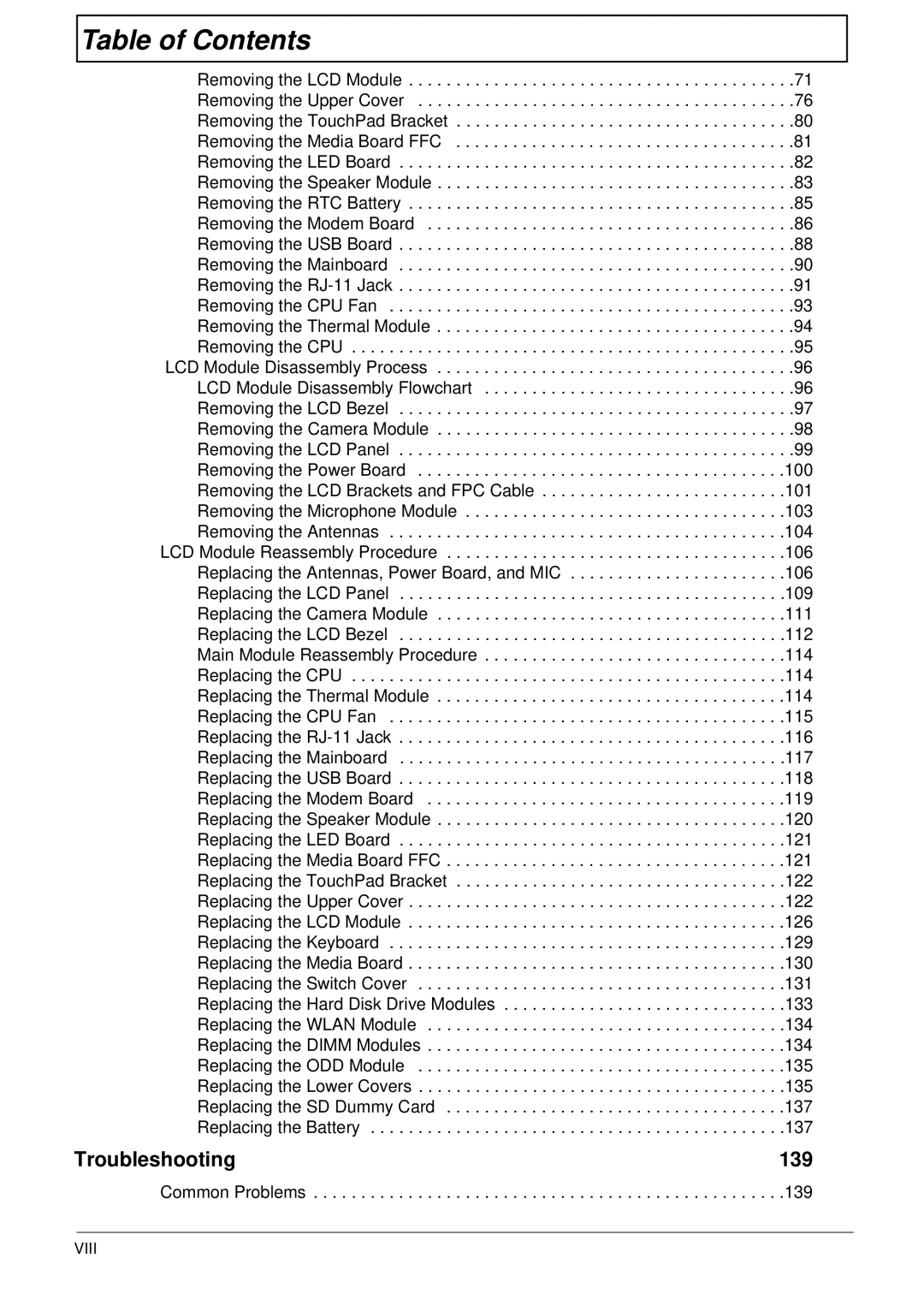
Table of Contents |
|
Removing the LCD Module | . .71 |
Removing the Upper Cover | . .76 |
Removing the TouchPad Bracket | . .80 |
Removing the Media Board FFC | . .81 |
Removing the LED Board | . .82 |
Removing the Speaker Module | . .83 |
Removing the RTC Battery | . .85 |
Removing the Modem Board | . .86 |
Removing the USB Board | . .88 |
Removing the Mainboard | . .90 |
Removing the | . .91 |
Removing the CPU Fan | . .93 |
Removing the Thermal Module | . .94 |
Removing the CPU | . .95 |
LCD Module Disassembly Process | . .96 |
LCD Module Disassembly Flowchart | . .96 |
Removing the LCD Bezel | . .97 |
Removing the Camera Module | . .98 |
Removing the LCD Panel | . .99 |
Removing the Power Board | .100 |
Removing the LCD Brackets and FPC Cable | .101 |
Removing the Microphone Module | .103 |
Removing the Antennas | .104 |
LCD Module Reassembly Procedure | .106 |
Replacing the Antennas, Power Board, and MIC | .106 |
Replacing the LCD Panel | .109 |
Replacing the Camera Module | .111 |
Replacing the LCD Bezel | .112 |
Main Module Reassembly Procedure | .114 |
Replacing the CPU | .114 |
Replacing the Thermal Module | .114 |
Replacing the CPU Fan | .115 |
Replacing the | .116 |
Replacing the Mainboard | .117 |
Replacing the USB Board | .118 |
Replacing the Modem Board | .119 |
Replacing the Speaker Module | .120 |
Replacing the LED Board | .121 |
Replacing the Media Board FFC | .121 |
Replacing the TouchPad Bracket | .122 |
Replacing the Upper Cover | .122 |
Replacing the LCD Module | .126 |
Replacing the Keyboard | .129 |
Replacing the Media Board | .130 |
Replacing the Switch Cover | .131 |
Replacing the Hard Disk Drive Modules | .133 |
Replacing the WLAN Module | .134 |
Replacing the DIMM Modules | .134 |
Replacing the ODD Module | .135 |
Replacing the Lower Covers | .135 |
Replacing the SD Dummy Card | .137 |
Replacing the Battery | .137 |
Troubleshooting | 139 |
Common Problems . . . . . . . . . . . . . . . . . . . . . . . . . . . . . . . . . . . . . . . . . . . . . . . . . .139
