Recording With an External VTR Instead of the Internal VTR
Using the 26-pin/12-pin Output Adaptor
Connections
The method of connecting the external VTR is the same as that described in “Recording Simulta- neously with the Internal VTR and an External VTR”.
ÁSee “Connections” on page 101.
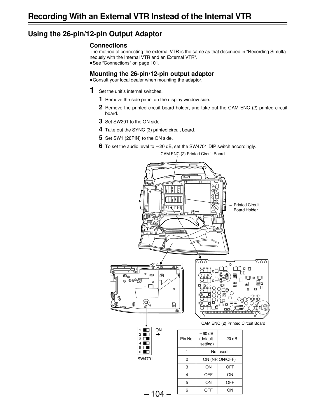
Mounting the 26-pin/12-pin output adaptor
ÁConsult your local dealer when mounting the adaptor.
1 Set the unit’s internal switches.
1Remove the side panel on the display window side.
2Remove the printed circuit board holder, and take out the CAM ENC (2) printed circuit board.
3Set SW201 to the ON side.
4Take out the SYNC (3) printed circuit board.
5Set SW1 (26PIN) to the ON side.
6To set the audio level to p20 dB, set the SW4701 DIP switch accordingly.
CAM ENC (2) Printed Circuit Board
![]() Printed Circuit
Printed Circuit
Board Holder
![]()
![]()
![]()
![]()
![]()
![]() SONY N
SONY N![]()
MII
SW1
SW201
ON OFF
|
|
|
| CAM ENC (2) Printed Circuit Board | ||
1 |
| ON |
|
|
|
|
| p60 dB |
|
| |||
2 |
|
|
|
|
| |
3 |
|
| Pin No. | (default | p20 dB |
|
4 |
|
|
| setting) |
|
|
5 |
|
|
|
|
|
|
| 1 | Not used |
| |||
6 |
|
|
| |||
SW4701 |
|
|
|
|
| |
| 2 | ON (NR ON/OFF) |
| |||
|
|
|
|
|
|
|
|
|
| 3 | ON | OFF |
|
|
|
|
|
|
|
|
|
|
| 4 | OFF | ON |
|
|
|
|
|
|
|
|
|
|
| 5 | ON | OFF |
|
|
|
|
|
|
|
|
– 104 – | 6 | OFF | ON |
| ||
|
|
|
| |||
|
|
|
| |||