Indoor Pan/Tilt Head
Parts and their function
=Guide pin
Use this to determine the direction in which the camera is to be mounted.
>Camera mounting screws (U1/4” 20UNC)
These are used to secure the camera firmly after it has been mounted.
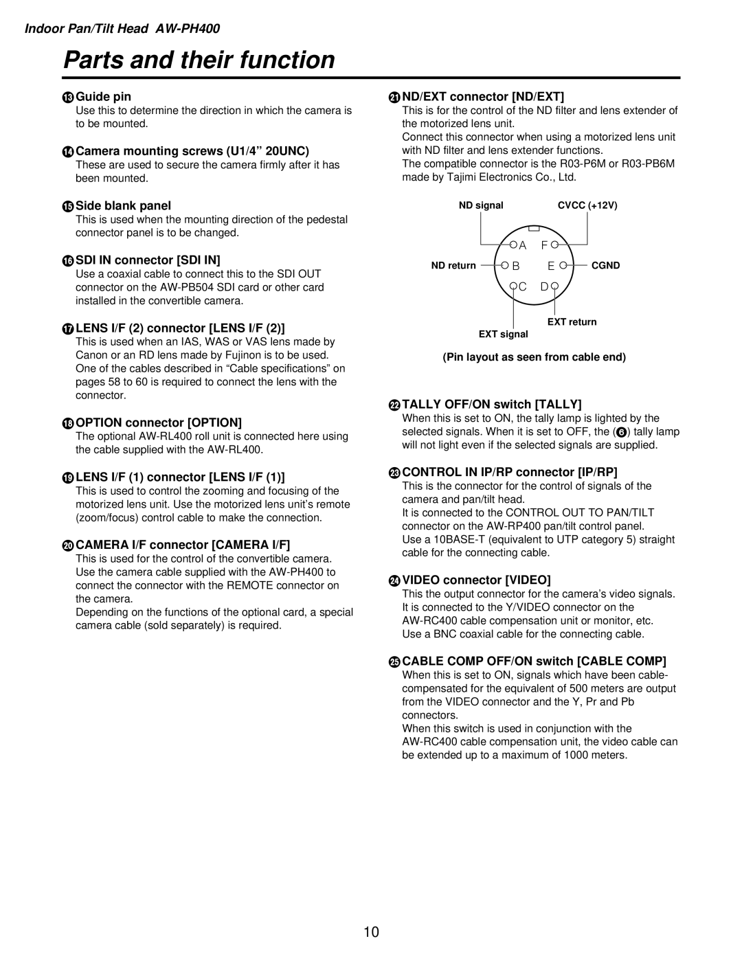
END/EXT connector [ND/EXT]
This is for the control of the ND filter and lens extender of the motorized lens unit.
Connect this connector when using a motorized lens unit with ND filter and lens extender functions.
The compatible connector is the
?Side blank panel
ND signal | CVCC (+12V) |
This is used when the mounting direction of the pedestal connector panel is to be changed.
A F
@SDI IN connector [SDI IN]
Use a coaxial cable to connect this to the SDI OUT connector on the
ALENS I/F (2) connector [LENS I/F (2)]
This is used when an IAS, WAS or VAS lens made by Canon or an RD lens made by Fujinon is to be used. One of the cables described in “Cable specifications” on pages 58 to 60 is required to connect the lens with the connector.
BOPTION connector [OPTION]
The optional
ND return | B | E | CGND |
C D
EXT return
EXT signal
(Pin layout as seen from cable end)
FTALLY OFF/ON switch [TALLY]
When this is set to ON, the tally lamp is lighted by the selected signals. When it is set to OFF, the (6) tally lamp will not light even if the selected signals are supplied.
CLENS I/F (1) connector [LENS I/F (1)]
This is used to control the zooming and focusing of the motorized lens unit. Use the motorized lens unit’s remote (zoom/focus) control cable to make the connection.
DCAMERA I/F connector [CAMERA I/F]
This is used for the control of the convertible camera. Use the camera cable supplied with the
Depending on the functions of the optional card, a special camera cable (sold separately) is required.
GCONTROL IN IP/RP connector [IP/RP]
This is the connector for the control of signals of the camera and pan/tilt head.
It is connected to the CONTROL OUT TO PAN/TILT connector on the
Use a
HVIDEO connector [VIDEO]
This the output connector for the camera’s video signals. It is connected to the Y/VIDEO connector on the
ICABLE COMP OFF/ON switch [CABLE COMP]
When this is set to ON, signals which have been cable- compensated for the equivalent of 500 meters are output from the VIDEO connector and the Y, Pr and Pb connectors.
When this switch is used in conjunction with the
10