Description of Parts
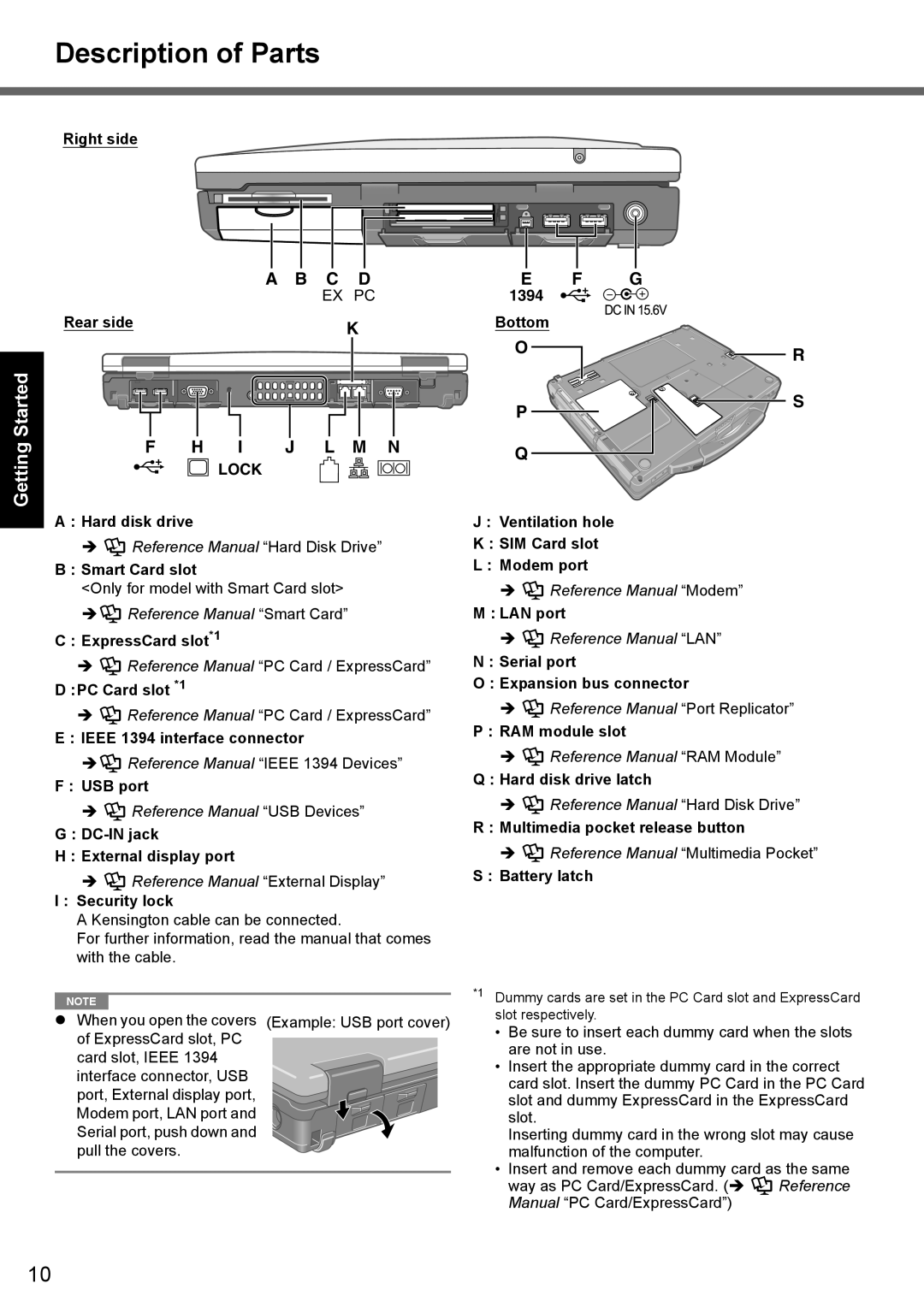
Right side
A | B | C | D |
|
| EX PC | |
Rear side |
|
| K |
E | F | G |
1394 |
|
|
Bottom |
|
|
Getting Started
|
|
|
|
|
|
| O | R |
|
|
|
|
|
|
|
| |
|
|
|
|
|
|
| P | S |
|
|
|
|
|
|
|
| |
F | H | I | J | L | M | N | Q |
|
|
| LOCK |
|
|
|
|
| |
|
|
|
|
|
|
|
|
A : Hard disk drive
![]() Reference Manual “Hard Disk Drive”
Reference Manual “Hard Disk Drive”
B : Smart Card slot
<Only for model with Smart Card slot>
![]() Reference Manual “Smart Card”
Reference Manual “Smart Card”
C : ExpressCard slot*1
Reference Manual “PC Card / ExpressCard”
D :PC Card slot *1
![]() Reference Manual “PC Card / ExpressCard”
Reference Manual “PC Card / ExpressCard”
E : IEEE 1394 interface connector
![]() Reference Manual “IEEE 1394 Devices”
Reference Manual “IEEE 1394 Devices”
F : USB port
![]() Reference Manual “USB Devices”
Reference Manual “USB Devices”
G:
H: External display port
Reference Manual “External Display”
I : Security lock
A Kensington cable can be connected.
For further information, read the manual that comes with the cable.
J : Ventilation hole
K : SIM Card slot
L : Modem port
![]() Reference Manual “Modem”
Reference Manual “Modem”
M : LAN port
 Reference Manual “LAN”
N : Serial port
O : Expansion bus connector
![]() Reference Manual “Port Replicator”
Reference Manual “Port Replicator”
P : RAM module slot
![]() Reference Manual “RAM Module”
Reference Manual “RAM Module”
Q : Hard disk drive latch
![]() Reference Manual “Hard Disk Drive”
Reference Manual “Hard Disk Drive”
R : Multimedia pocket release button
![]() Reference Manual “Multimedia Pocket”
Reference Manual “Multimedia Pocket”
S : Battery latch
NOTE | *1 | Dummy cards are set in the PC Card slot and ExpressCard | ||
When you open the covers | (Example: USB port cover) | slot respectively. |
| |
• Be sure to insert each dummy card when the slots | ||||
of ExpressCard slot, PC |
| |||
| are not in use. |
| ||
card slot, IEEE 1394 |
|
| ||
| • Insert the appropriate dummy card in the correct | |||
interface connector, USB |
| |||
| card slot. Insert the dummy PC Card in the PC Card | |||
port, External display port, |
| |||
| slot and dummy ExpressCard in the ExpressCard | |||
Modem port, LAN port and |
| |||
| slot. |
| ||
Serial port, push down and |
| Inserting dummy card in the wrong slot may cause | ||
pull the covers. |
| malfunction of the computer. |
| |
|
| • Insert and remove each dummy card as the same | ||
|
| way as PC Card/ExpressCard. ( | Reference | |
|
| Manual “PC Card/ExpressCard”) |
| |
10