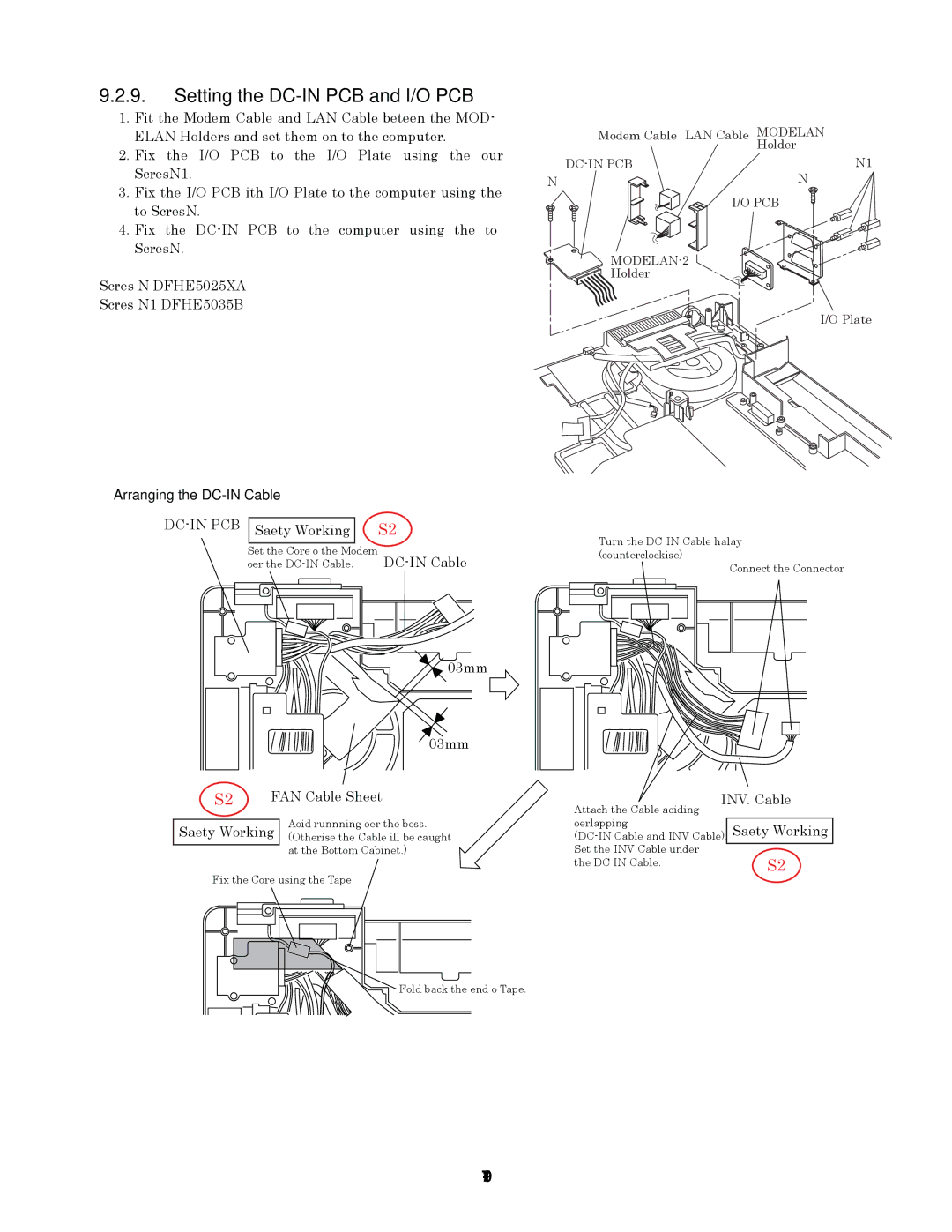
9.2.9.Setting the DC-IN PCB and I/O PCB
1.Fit the Modem Cable and LAN Cable between the MOD- ELAN Holders, and set them on to the computer.
2.Fix the I/O PCB to the I/O Plate using the four Screws<N19>.
3.Fix the I/O PCB with I/O Plate to the computer using the two Screws<N9>.
4.Fix the
Screws <N9>: DFHE5025XA
Screws <N19>: DFHE5035ZB
Modem Cable LAN Cable | MODELAN |
| Holder |
<N19> | |
<N9> | <N9> |
I/O PCB
Holder
I/O Plate
Arranging the DC-IN Cable
DC-IN PCB
S2
| Safety Working |
| S2 |
|
|
|
|
| Set the Core of the Modem | ||
over the | |||
 0~3mm
0~3mm
0~3mm
FAN Cable Sheet
Turn the
Connect the Connector
INV. Cable |
Attach the Cable avoiding |
Avoid runnning over the boss.
Safety Working (Otherwise the Cable will be caught at the Bottom Cabinet.)
Fix the Core using the Tape.
Fold back the end of Tape.
overlapping | Safety Working |
Set the INV Cable under |
|
the DC IN Cable. | S2 |