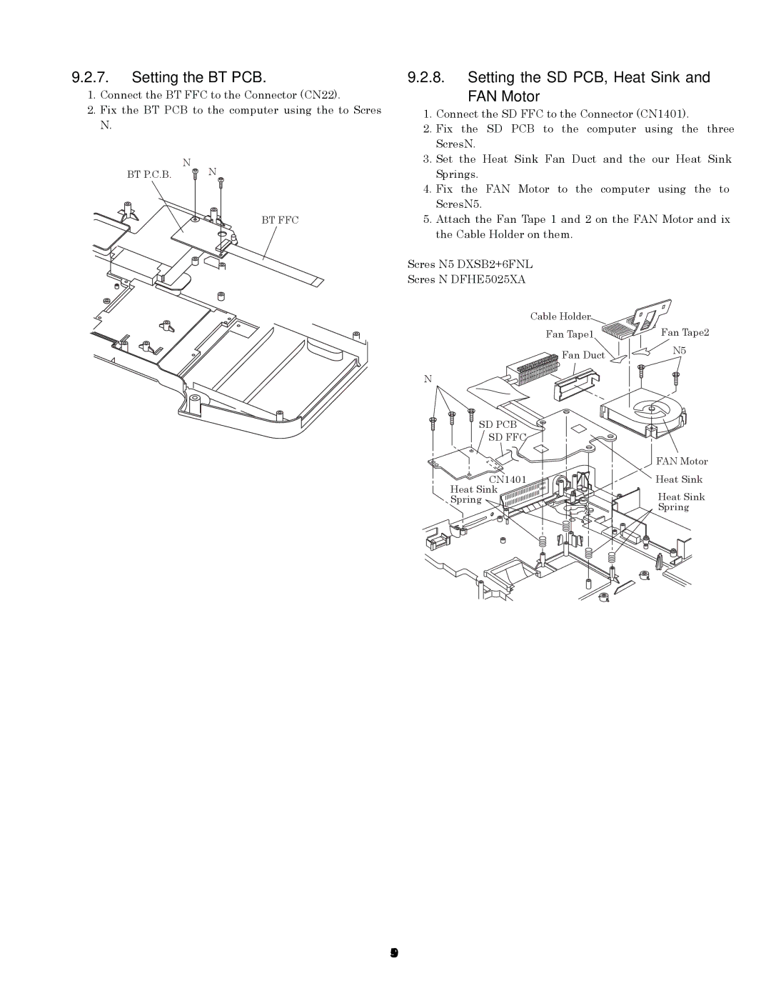
9.2.7.Setting the BT PCB.
1.Connect the BT FFC to the Connector (CN22).
2.Fix the BT PCB to the computer using the two Screws <N9>.
BT P.C.B. <N9><N9>
BT FFC
9.2.8.Setting the SD PCB, Heat Sink and
FAN Motor
1.Connect the SD FFC to the Connector (CN1401).
2.Fix the SD PCB to the computer using the three Screws<N9>.
3.Set the Heat Sink, Fan Duct and the four Heat Sink Springs.
4.Fix the FAN Motor to the computer using the two Screws<N5>.
5.Attach the Fan Tape 1 and 2 on the FAN Motor, and fix the Cable Holder on them.
Screws <N5>: DXSB2+6FNL
Screws <N9>: DFHE5025XA
Cable Holder |
|
Fan Tape1 | Fan Tape2 |
Fan Duct | <N5> |
|
<N9>
SD PCB
SD FFC |
|
| FAN Motor |
CN1401 | Heat Sink |
Heat Sink | Heat Sink |
Spring | |
| Spring |