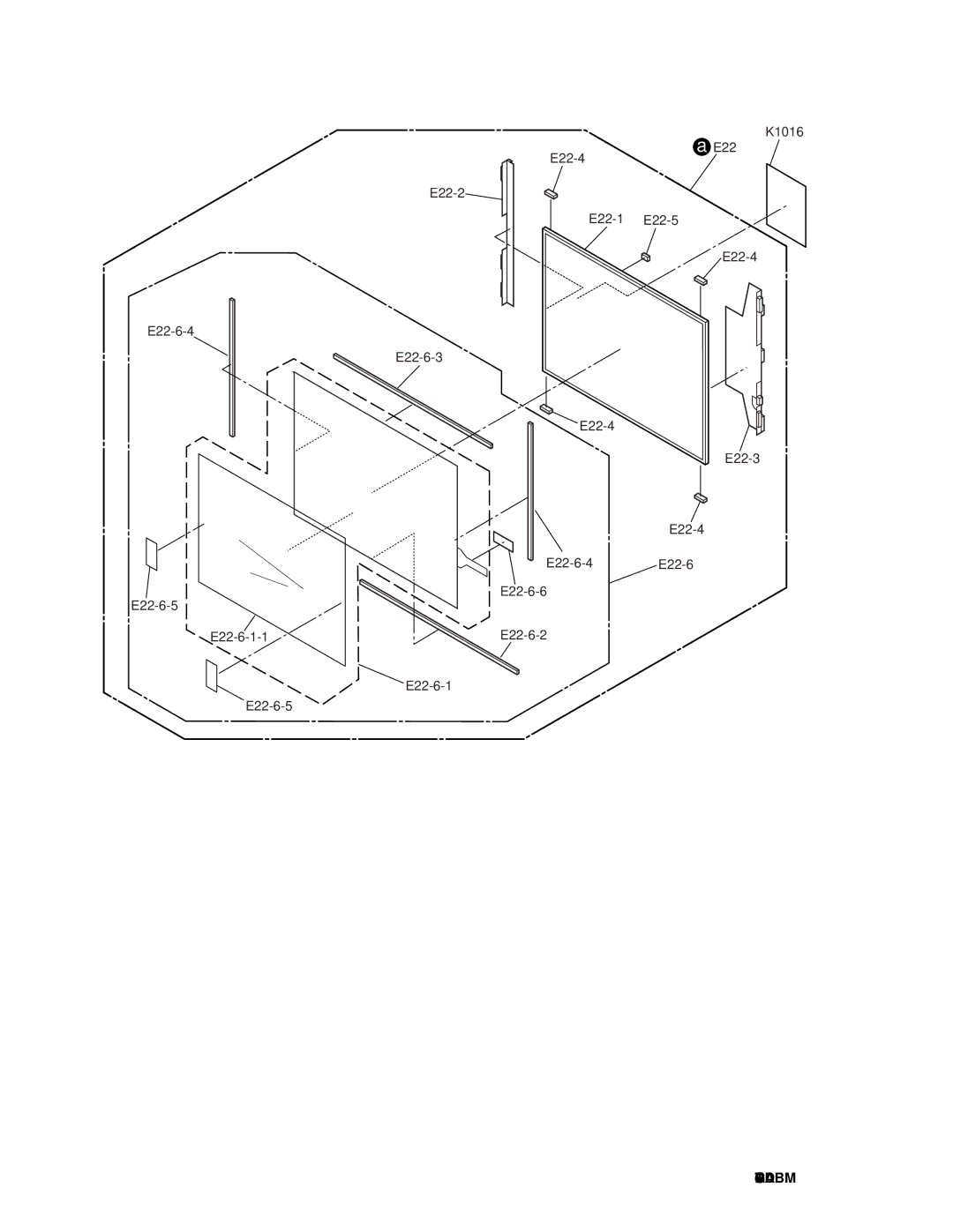
Manuals
/
Brands
/
Computer Equipment
/
Laptop
/
Panasonic
/
Computer Equipment
/
Laptop
Panasonic
CF-74GCDADBM service manual
a
1
51
64
64
Download
64 pages, 1.74 Mb
CF-74GCDADBM
E22-6-6
E22-6-3
E22-1
E22-2
E22-3
E22-4
E22-4
E22-4
E22-4
E22-5
E22
E22-6-2
E22-6-4
E22-6-4
E22-6
E22-6-1-1
E22-6-1
E22-6-5
E22-6-5
a
K1016
Contents
Main
Page
LASER SAFETY INFORMATION
Page
Page
CONTENTS
1. Specifications
1-1
Main Specifications
1-2
Main Specifications
Wireless LAN <Only for model with wireless LAN>
Bluetooth <Only for model with Bluetooth>
1-3
2. Names and Functions of Parts
2-2
EX PC
3 Block Diagram
DDR2 SDRAM
18bit
XGA
Page
4-2
5 Power-On Self Test (Boot Check)
Outline of POST
5-1
Error Diagnosis by Checking Beep Signal Sound
6 List of Error Codes
<Only when the port replicator is connected>
6-1
6-2
7 Self Diagnosis Test
1
7-1
. Beginning of self-diagnosis test 1-1. Setting of content of setup
2. Operation of PC-Diagnostic Utility
7-2
Page
Page
8 Wiring Connection Diagram
I O PCB
DC-IN PCB
SD PCB
8-1
9 Disassembly/Reassembly
9.1. Disassembly Instructions
9.1.1. Preparation
9.1.2. Removing the Battery Pack, the HDD Unit and the DVD-ROM Drive Unit
9.1.3. Removing the HDD
9.1.4. Removing the DIMM Memory Card
9.1.5. Removing the Keyboard
9.1.6. Removing the Speaker and the LED PCB
9-3
9.1.7. Removing the Handle Ass'y
9.1.8. Removing the Bottom Case
9-4
9.1.9. Removing the Wireless Module and MDC Module
9.1.10. Removing the Main PCB
9.1.11. Removing the PC Card Ejector and Lithium Battery
9-5
9.1.12. Removing the DC-IN PCB and I/O PCB
9.1.13. Removing the FAN Motor and SD PCB
9.1.14. Removing the BT PCB
9-6
9.1.15. Removing the USB PCB
9.1.16. Removing the Display unit
9.1.18. Removing the LCD and the Inverter
9.1.17. Removing the LCD Front Cabinet
9-7
9.1.19. Removing the Touch PAD and PAD PCB
9.1.20. Removing the Finger PCB
9-8
9.2. Reassembly Instructions
9.2.1. Attention when CF-74 series is repaired
9.2.2. Setting the Finger PCB
9.2.3. Setting the LCD Unit and the Inverter
9-9
0~1mm
LCD Damper C
LCD Unit
9-10
S1
9-11
S5
S1
Arranging the TP Power Cable and Attaching the TP/LCD Sheet
S2
9-12
9-13
9.2.4. Setting the LCD Front Cabinet
9.2.5. Setting the Display unit
9-14
9.2.6. Setting the USB PCB
S2
9-15
9.2.7. Setting the BT PCB.
9.2.8. Setting the SD PCB, Heat Sink and FAN Mo tor
9-16
9-17
9.2.9. Setting the DC-IN PCB and I/O PCB
9-18
9.2.10. Setting the PC Card Ejector and Lithium Battery
9.2.11. Setting the Main PCB
S2
9-19
Safety Working
FAN Cable
Connector (CN28)
9.2.12. Setting the Wireless Module and MDC Module
S2
<Preparation for assembly of the MDC Module>
Arranging the Modem Cable
S1
9.2.13. Setting the Bottom Case
9.2.14. Setting the Handle Ass'y
9-22
9.2.15. Setting the Speaker and the LED PCB
S3
9-23
9.2.16. Setting the Keyboard
S2
9-24
9.2.17. Setting the DIMM Memory Card and DIMM Cover
9.2.18. Setting the HDD
Page
10 Exploded View
Screw tightening torque
a
a
Replacement Parts List
CF-74GCDADBM
REF. NO andAREA
Page
Page
Page
Replacement Parts List
CF-74GCDADBM
REF. NO and AREA
MAIN PCB
!
Page
Page
Page
Page
Page
Page
IO PCB
LED PCB
USB PCB
DC-IN PCB
TOUCH SCREEN PCB
SD PCB
PAD/SWITCH PCB
BLUETOOTH PCB