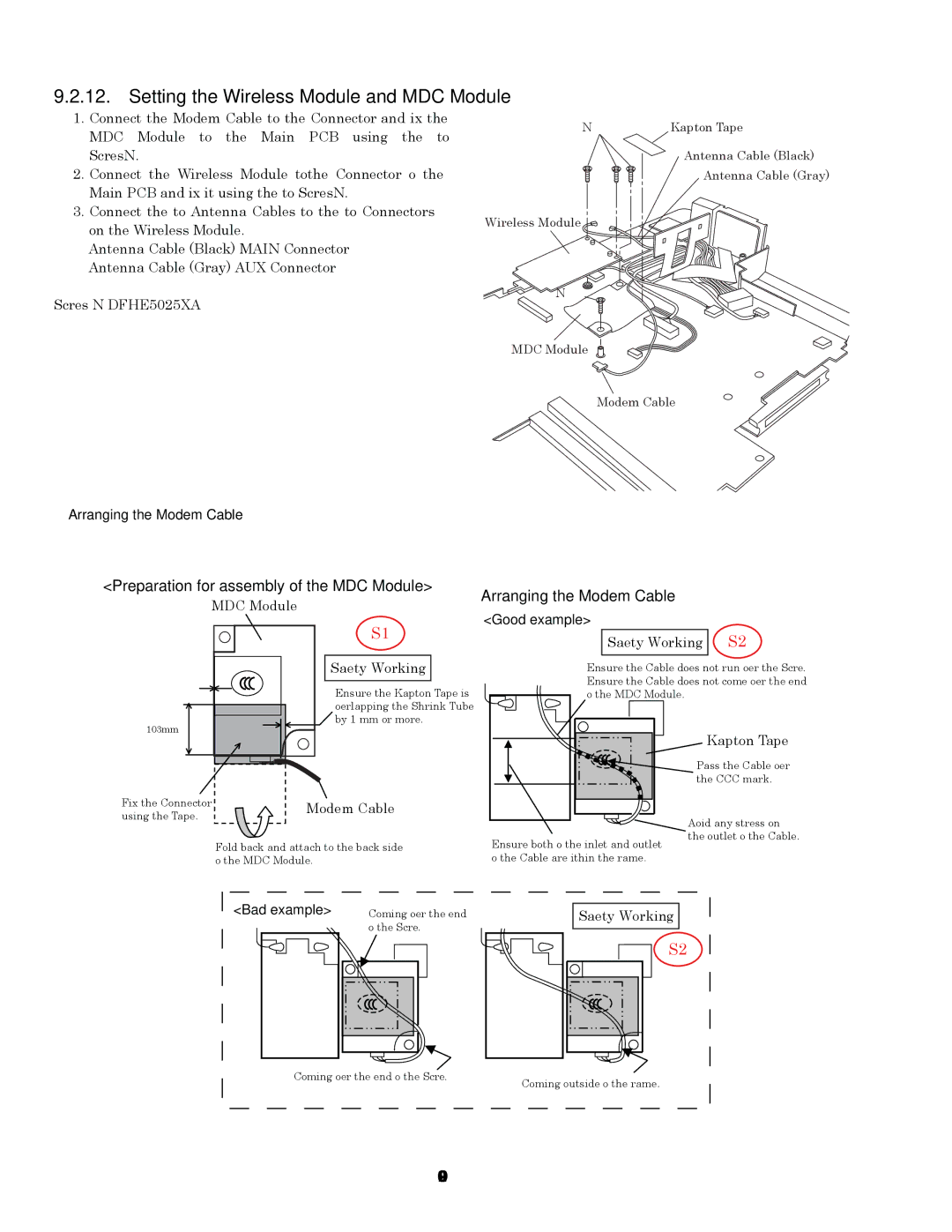
9.2.12. Setting the Wireless Module and MDC Module
1.Connect the Modem Cable to the Connector, and fix the MDC Module to the Main PCB using the two Screws<N9>.
2.Connect the Wireless Module to the Connector of the Main PCB, and fix it using the two Screws<N9>.
3.Connect the two Antenna Cables to the two Connectors on the Wireless Module.
•Antenna Cable (Black): MAIN Connector
•Antenna Cable (Gray): AUX Connector
Screws <N9>: DFHE5025XA
<N9> | Kapton Tape |
Antenna Cable (Black)
Antenna Cable (Gray)
Wireless Module
<N9>
MDC Module
Modem Cable
Arranging the Modem Cable
<Preparation for assembly of the MDC Module>
Arranging the Modem Cable
MDC Module
S1
Safety Working
Ensure the Kapton Tape is overlapping the Shrink Tube by 1 mm or more.
<Good example>
Safety Working S2
Ensure the Cable does not run over the Screw. Ensure the Cable does not come over the end of the MDC Module.
Kapton Tape
Pass the Cable over the CCC mark.
Fix the Connector | Modem Cable | |
using the Tape. | ||
|
Fold back and attach to the back side of the MDC Module.
Ensure both of the inlet and outlet of the Cable are within the frame.
Avoid any stress on the outlet of the Cable.
<Bad example> |
Coming over the end of the Screw.
Safety Working
S2
Coming over the end of the Screw. | Coming outside of the frame. |
|