Operating Instructions Instrucciones de funcionamiento
Example Ejemplo
Started
Table of contents
Useful features
Accessories
Remote control
Please check and identify the supplied accessories
Batteries
Remote control
Control reference guide
Main unit
Unit’s display
Do not connect the unit through a video cassette recorder
When the unit is not to be used for a long time
Recommended connection for your television
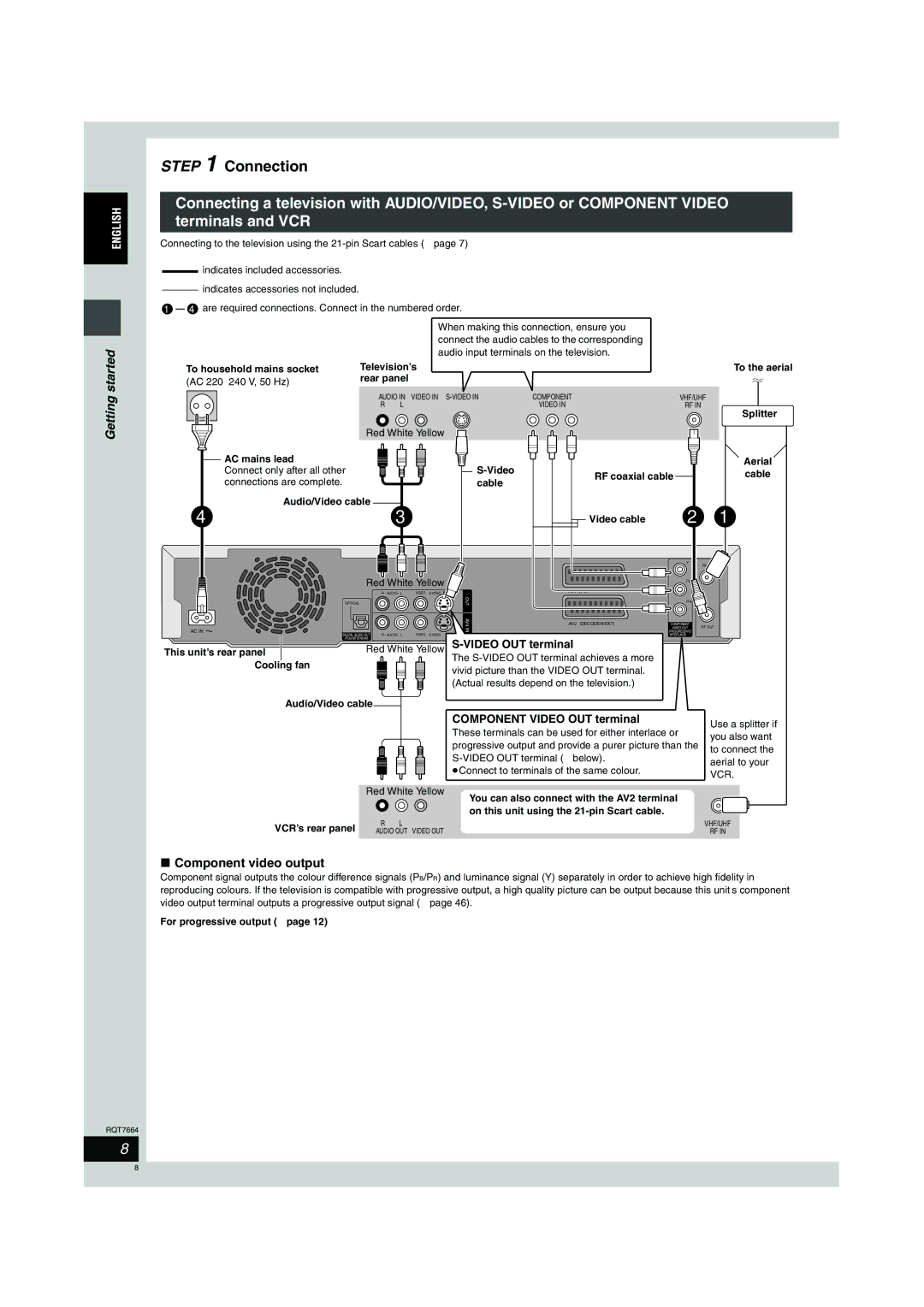
Connecting a television with 21-pin Scart terminal and VCR
AV1 terminal
Connection
Component video output
Video OUT terminal
Component Video OUT terminal
Connection to a stereo amplifier
Connecting an amplifier or system component
To enjoy multi-channel surround sound on DVD-Video
Preset Download Setup with Q Link functions
If the clock setting menu appears
Enter
Return
Auto-Setup Setup without Q Link functions
Country setting menu appears
Auto-Setup starts. This takes about 8 minutes
Auto-Setup is complete when you see the television picture
Press 3, 4, 2, 1 to select Setup and press Enter
Selecting television type and aspect
Press Functions
To enjoy progressive video
When the following indicator appears on the unit’s display
Point the remote control at the television
To change the code on the remote control
Television operation
HDD and Disc information
HDD and discs you can use for recording and play
Play-only discs 12 cm/8 cm
Discs that cannot be played
HDD Hard disk drive handling care
Getting
Press ¥ REC to start recording
Recording television programmes
Press W X CH to select the channel
Direct TV Recording
Recording modes and approximate recording times
Playing while you are recording
Flexible Recording
Recording from an external equipment
Timer recording
Using Showview number to make timer recordings
Press F Timer
Press ShowView
Manually programming timer recordings
Press 3, 4 to select New Timer
Press PROG/CHECK
Press 1 to move through the items
Press EXT Link
Linked timer recordings with external equipment EXT Link
Check, change or delete a programme
Playing
Playing discs
Back
Operations during play
Skipping the specified
Time Time Slip
Manual Skip
Editing operations during play
Changing audio
Press Audio
Press Erase Press 2, 1 to select Erase and press Enter
Using menus to play MP3
Using the tree screen to find a group
Press 3, 4, 2, 1 to select a group
Press TOP Menu
Using on-screen menus and Status messages
Disc menu-Setting the disc content
On-screen menus
Press Display
Status messages
Press Status
Play menu-Change the play sequence
Picture menu-Change the picture quality
Editing titles/chapters
Editing titles/chapters and playing chapters
Press Direct Navigator Press 3, 4, 2, 1 to select the title
Press 3, 4, 2, 1 to select the chapter
Set up Protection §
Title operations
Press 2, 1 to select Yes and press Enter
Press Enter at the start point and end
Press 3 to cancel
Creating, editing and playing play lists
Press 3, 4, 2, 1 to select Play List and press Enter
Creating play lists
Editing and playing play lists/chapters
Play list operations
Move
Chapter
Entering text
Show Enter Name screen
Press 3, 4 To select a Character and press Enter
Press SET
Transferring dubbing titles or play lists
Transfer Dubbing
One Touch Transfer dubbing
Press Dubbing
Press Enter to confirm
Dubbing
Press 3, 4 to select Start Dubbing and press Enter
Transferring dubbing a finalized DVD-R
To edit the transferring dubbing list
Dubbing
Functions window
Press 3, 4, 2, 1 to select an item and press Enter
Press 3, 4, 2, 1 to select Disc Management and press Enter
Press 3, 4 to select the operation and press Enter
Disc Name
Top Menu
Disc Protection
Format Disc
Changing the unit’s settings
Common procedures
Summary of settings
Convenient functions
Tabs Menus Options Underlined items are the factory presets
Picture
Functions
AV2 Settings
TV Aspect
Progressive
TV System
Tuning
Press 3, 4 to select Manual and press Enter
Press 3, 4, 2
Programme position
Auto-Setup Restart
To change the setting all at once PAL!#NTSC
Press 3, 4, 2, 1 to select a country and press Enter
TV System
Clock settings
Child Lock
Specifications
Safety precautions
Glossary
When Showview
When programming
Link
Message Message appears when
Frequently asked questions
Set upPage
Cover
Recording
On the unit’s display
Error messages
On the television
Troubleshooting guide
Following do not indicate a problem with this unit
Breaks
≥Set the clock Display
Low volume
Cannot switch audio
Remote control doesn’t
Sound No sound
Troubleshooting guide
Disc handling
Maintenance
Unit care
Index
RGB