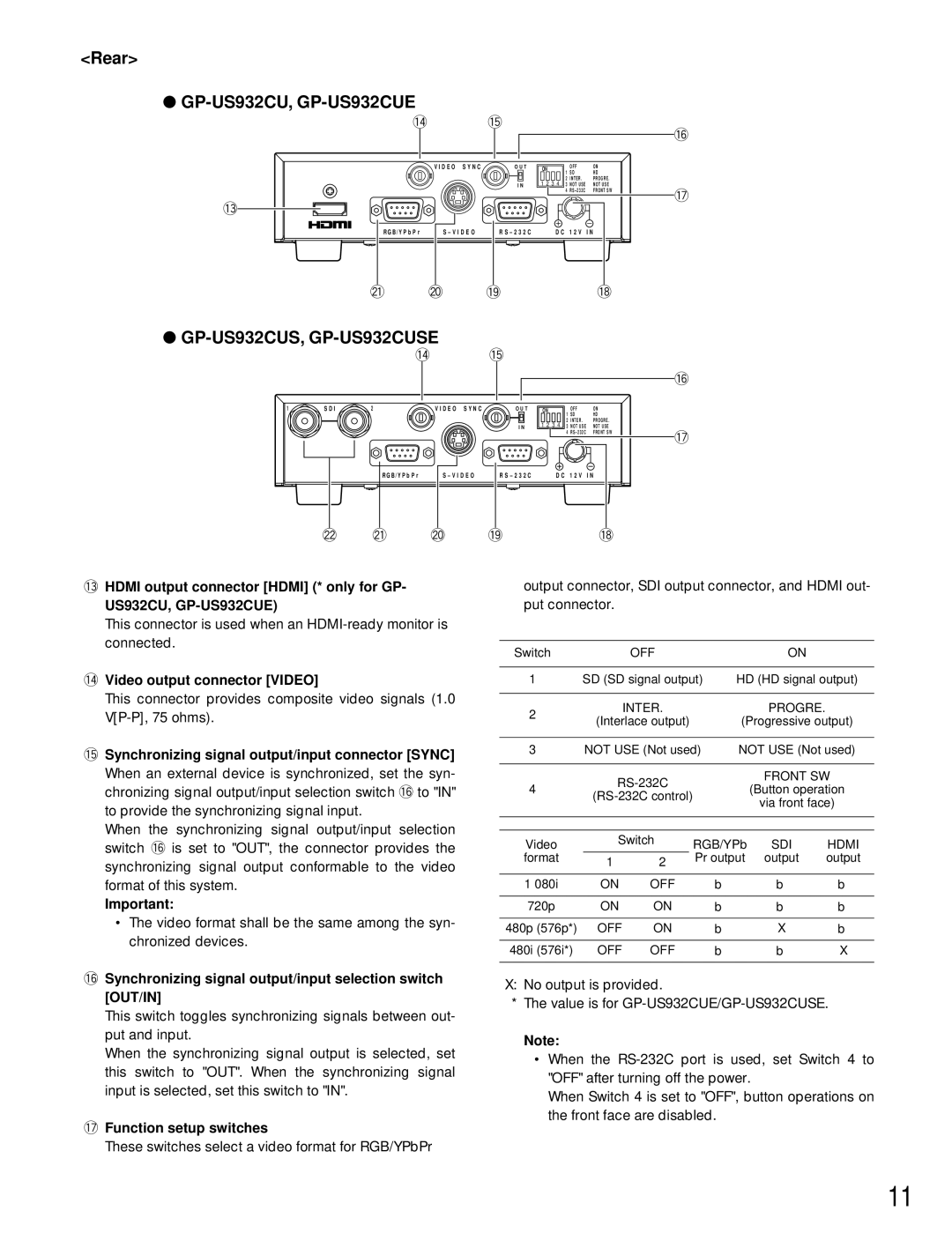
<Rear>
● |
|
|
|
|
|
|
|
|
!4 |
| !5 |
|
|
|
| !6 | |
|
|
|
|
|
|
|
| |
| V I D E O | S Y N C | O U T | ON | 1 | OFF | O N |
|
|
|
|
| SD | H D |
| ||
|
|
|
|
|
| |||
|
|
|
| 1 2 3 4 | 2 | INTER . | P R O G R E . |
|
|
|
| I N | 3 | NOT USE | NOT USE |
| |
|
|
|
|
| 4 | RS – 232C | FRONT SW | !7 |
!3 |
|
|
|
|
|
|
| |
|
|
|
|
|
|
|
| |
R G B / Y P b P r | S – V I D E O | R S – 2 3 2 C | D C 1 2 V I N |
|
| |||
@1 | @0 |
| !9 |
|
|
| !8 |
|
●GP-US932CUS, GP-US932CUSE
!4 !5
!6
1 | S D I | 2 | V I D E O | S Y N C | O U T | ON | 1 | OFF | O N |
|
|
|
|
|
|
|
| SD | H D |
| |
|
|
|
|
|
| 1 2 3 4 | 2 | INTER . | P R O G R E . |
|
|
|
|
|
| I N | 3 | NOT USE | NOT USE |
| |
|
|
|
|
|
|
| 4 | RS – 232C | FRONT SW | !7 |
|
|
|
|
|
|
|
|
|
| |
|
| R G B / Y P b P r | S – V I D E O | R S – 2 3 2 C | D C 1 2 V I N |
| ||||
@2 @1 @0
!3HDMI output connector [HDMI] (* only for GP-
US932CU, GP-US932CUE)
This connector is used when an
!4Video output connector [VIDEO]
This connector provides composite video signals (1.0
!5Synchronizing signal output/input connector [SYNC]
When an external device is synchronized, set the syn- chronizing signal output/input selection switch !6to "IN" to provide the synchronizing signal input.
When the synchronizing signal output/input selection switch !6is set to "OUT", the connector provides the synchronizing signal output conformable to the video format of this system.
Important:
•The video format shall be the same among the syn- chronized devices.
!9 !8
output connector, SDI output connector, and HDMI out- put connector.
Switch |
| OFF |
|
| ON |
| |
|
|
|
| ||||
1 | SD (SD signal output) | HD (HD signal output) | |||||
|
|
|
|
|
|
|
|
2 |
| INTER. |
|
| PROGRE. |
| |
(Interlace output) |
| (Progressive output) | |||||
|
| ||||||
|
|
|
| ||||
3 | NOT USE (Not used) | NOT USE (Not used) | |||||
|
|
|
|
|
|
| |
|
|
| FRONT SW | ||||
4 |
|
| (Button operation | ||||
|
| ||||||
|
|
| via front face) | ||||
|
|
|
|
|
| ||
|
|
|
|
|
|
| |
|
|
|
|
|
|
| |
Video | Switch | RGB/YPb | SDI | HDMI | |||
|
|
| |||||
format | 1 | 2 |
| Pr output | output | output | |
|
|
|
|
|
| ||
|
|
|
|
|
|
| |
1 080i | ON | OFF | b |
| b | b | |
720p | ON | ON | b |
| b | b | |
480p (576p*) | OFF | ON | b |
| X | b | |
480i (576i*) | OFF | OFF | b |
| b | X | |
!6Synchronizing signal output/input selection switch [OUT/IN]
This switch toggles synchronizing signals between out- put and input.
When the synchronizing signal output is selected, set this switch to "OUT". When the synchronizing signal input is selected, set this switch to "IN".
!7Function setup switches
These switches select a video format for RGB/YPbPr
X: No output is provided.
*The value is for
Note:
•When the
When Switch 4 is set to "OFF", button operations on the front face are disabled.
11