PRECAUTIONS IN USING THE COUNTER
Cautions for circuits
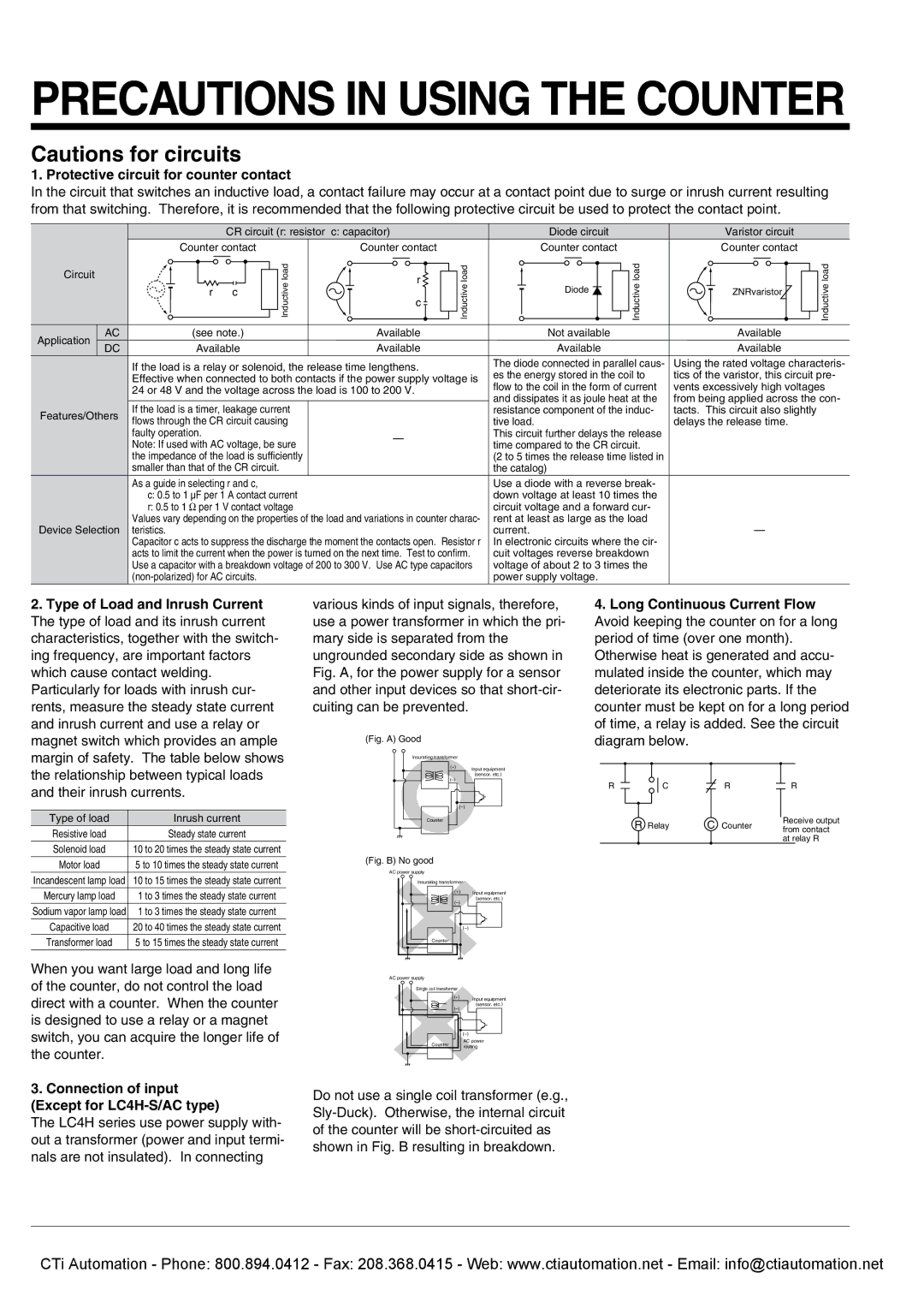
1. Protective circuit for counter contact
In the circuit that switches an inductive load, a contact failure may occur at a contact point due to surge or inrush current resulting from that switching. Therefore, it is recommended that the following protective circuit be used to protect the contact point.
|
| CR circuit (r: resistor | c: capacitor) |
| Diode circuit |
| Varistor circuit |
| |
| Counter contact |
| Counter contact |
| Counter contact |
| Counter contact |
| |
Circuit |
|
| load | r | load |
| load |
| load |
|
|
| Inductive | Inductive | Diode | Inductive |
| Inductive | |
| r | c | c | ZNRvaristor | |||||
|
|
|
|
| |||||
|
|
|
|
|
| ||||
AC | (see note.) |
| Available |
| Not available |
| Available |
| |
Application | Available |
| Available |
| Available |
| Available |
| |
DC |
|
|
|
| |||||
| If the load is a relay or solenoid, the release time lengthens. | The diode connected in parallel caus- | Using the rated voltage characteris- | |
| es the energy stored in the coil to | tics of the varistor, this circuit pre- | ||
| Effective when connected to both contacts if the power supply voltage is | |||
| flow to the coil in the form of current | vents excessively high voltages | ||
| 24 or 48 V and the voltage across the load is 100 to 200 V. | |||
| and dissipates it as joule heat at the | from being applied across the con- | ||
|
|
| ||
Features/Others | If the load is a timer, leakage current |
| resistance component of the induc- | tacts. This circuit also slightly |
flows through the CR circuit causing |
| tive load. | delays the release time. | |
|
| |||
| faulty operation. | — | This circuit further delays the release |
|
| Note: If used with AC voltage, be sure | time compared to the CR circuit. |
| |
|
|
| ||
| the impedance of the load is sufficiently |
| (2 to 5 times the release time listed in |
|
| smaller than that of the CR circuit. |
| the catalog) |
|
| As a guide in selecting r and c, |
| Use a diode with a reverse break- |
|
| c: 0.5 to 1 µF per 1 A contact current |
| down voltage at least 10 times the |
|
| r: 0.5 to 1 Ω per 1 V contact voltage |
| circuit voltage and a forward cur- |
|
| Values vary depending on the properties of the load and variations in counter charac- | rent at least as large as the load | — | |
Device Selection teristics. |
| current. | ||
| Capacitor c acts to suppress the discharge the moment the contacts open. Resistor r | In electronic circuits where the cir- |
| |
| acts to limit the current when the power is turned on the next time. Test to confirm. | cuit voltages reverse breakdown |
| |
| Use a capacitor with a breakdown voltage of 200 to 300 V. Use AC type capacitors | voltage of about 2 to 3 times the |
| |
|
| power supply voltage. |
| |
2.Type of Load and Inrush Current The type of load and its inrush current characteristics, together with the switch- ing frequency, are important factors which cause contact welding. Particularly for loads with inrush cur- rents, measure the steady state current and inrush current and use a relay or magnet switch which provides an ample margin of safety. The table below shows the relationship between typical loads and their inrush currents.
Type of load | Inrush current |
Resistive load | Steady state current |
Solenoid load | 10 to 20 times the steady state current |
Motor load | 5 to 10 times the steady state current |
Incandescent lamp load | 10 to 15 times the steady state current |
Mercury lamp load | 1 to 3 times the steady state current |
Sodium vapor lamp load | 1 to 3 times the steady state current |
Capacitive load | 20 to 40 times the steady state current |
Transformer load | 5 to 15 times the steady state current |
When you want large load and long life of the counter, do not control the load direct with a counter. When the counter is designed to use a relay or a magnet switch, you can acquire the longer life of the counter.
3.Connection of input (Except for LC4H-S/AC type)
The LC4H series use power supply with- out a transformer (power and input termi- nals are not insulated). In connecting
various kinds of input signals, therefore, use a power transformer in which the pri- mary side is separated from the ungrounded secondary side as shown in Fig. A, for the power supply for a sensor and other input devices so that
(Fig. A) Good
Insurating transformer
(+) | Input equipment |
(sensor, etc.) | |
| |
|
Counter
(Fig. B) No good |
|
AC power supply |
|
Insurating transformer |
|
(+) | Input equipment |
(sensor, etc.) | |
| |
| |
Counter |
|
AC power supply
Single coil transformer |
| |
(+) | Input equipment | |
| ||
(sensor, etc.) | ||
| ||
| ||
Counter | AC power | |
routing | ||
|
Do not use a single coil transformer (e.g.,
4.Long Continuous Current Flow Avoid keeping the counter on for a long period of time (over one month). Otherwise heat is generated and accu- mulated inside the counter, which may deteriorate its electronic parts. If the counter must be kept on for a long period of time, a relay is added. See the circuit diagram below.
R | C | R | R |
| R Relay | C Counter | Receive output |
| from contact | ||
|
|
| at relay R |
CTi Automation - Phone: 800.894.0412 - Fax: 208.368.0415 - Web: www.ctiautomation.net - Email: info@ctiautomation.net