MailConsumerproducts@Panasonic.com
Model PV-HS3000
Moving a product-and-cart combination
Outdoor antenna grounding
Do not place heavy objects on the Hard Disk Recorder
Patent Nos ,631,603.4,577,216.4,819,098 and 4,907,093
Precautions
Table of Contents
Welcome to the Hard Disk Recorder
Installing the Batteries
Before Using
Important Notes
Using wireless phone jacks
Connecting the incoming television signal
Basic Connections
Modifying an older type antenna
Connecting the telephone line
Connecting a composite-video television
Connecting the AC Power cord
Complete the on-screen setup
Planning Input and Output Connections
Advanced Connections
Connecting a Cable Box to the Hard Disk Recorder
Receiver
Satellite Receiver
OUT
Line Speaker OUT
Attaching Satellite Receiver and Cable Box Controllers
Connecting a Serial Cable
Locating the Infrared Detector On the Other Device
Connecting and Setting Up the IR Blaster
Turn on the television
Initial Setup
If the connection failed
Press Play to begin using the Hard Disk Recorder
Changing Your Setup Later On
Completing the IR Blaster Setup
Input Options
Press Number buttons
Press TV, then press Power to turn on your television
Using Instant Replay
Controlling Live Television
Viewing Live Television
Using Rewind and Fast Forward
Pausing Live Television and Recorded Shows
Using Frame Advance
Using Slow Motion
Using QuickSkip
Bypassing unwanted programming
Copy Protection Information
Viewing copy protected programming
Cable Box Splitter Hard Disk Recorder
Selecting a Show
Recording Shows
Channel Guide Screen Channel Guide Popup Menu Items
Press / / / to move around the guide
Recording a Single Upcoming Show
Watching and Recording a Show That Is Currently Airing
Press REC to record the show
Extending Recording Time
Cancelling a Recording
Recording Multiple Episodes of One Show
Recording is not in progress
Record Options Settings
Setting the Recording Options
Press Replay Zones to display the ReplayZones screen
Recording From Show Categories
Create a Theme , then press Select to select it
Recording Shows Based On a Theme You Choose
To Cancel Recording of a Show
To Record One of the Shows
To Create a Show-based Replay Channel
Finding Shows
Show-based Replay Channels
Finding All Episodes of a Show
Theme-based Replay Channels
Press Channel
Watching Your Recorded Shows
Seeing What a Replay Channel Will Record
Press Replay Guide to display the Replay Guide
Find matching shows, then press Select
Programming blocked by V-Chip technology
Watching a Show
Watching shows with closed-captioning
Press
Press / to select the show you want to save
Preserving a Show
Replay Guide, then press Select
Preserve this episode, then press
Saving Shows to Videotape
Press / to select Save to VCR, then press
Before you begin
Indication of Guaranteed or Non-guaranteed recording
Guaranteed and Non-guaranteed Recording
Managing Recording Space
Recording Priorities
Recording Space Management Tips
Guaranteed Record and Space-available Record
Changing Volume Lock
Universal Remote Control
Setting Up Your Components
To change the volume lock setting back to TV mode
Searching for Your Component’s Code
Re-assigning Component Mode Buttons
To reassign other component mode buttons
Learning the Codes Programmed Into the Remote
TVs
Code Numbers ForYour Components
VCRs
Code Numbers For Your Components
VCRs
Satellite Receivers
Cable Boxes
DVD Players
Laser Disks
Important Note
TV/VCR Combos
Problem Solution
Troubleshooting
When selecting a show in the Channel
Input Settings
Specifications
Specifications & Information
Resetting Hard Disk Recorder
Screen Burn
License Grant Restrictions
Software License Agreement
Panasonic Hard Disk Recorder Products Limited Warranty
Warranty
Regulatory Notices for the U.S
Service Center List
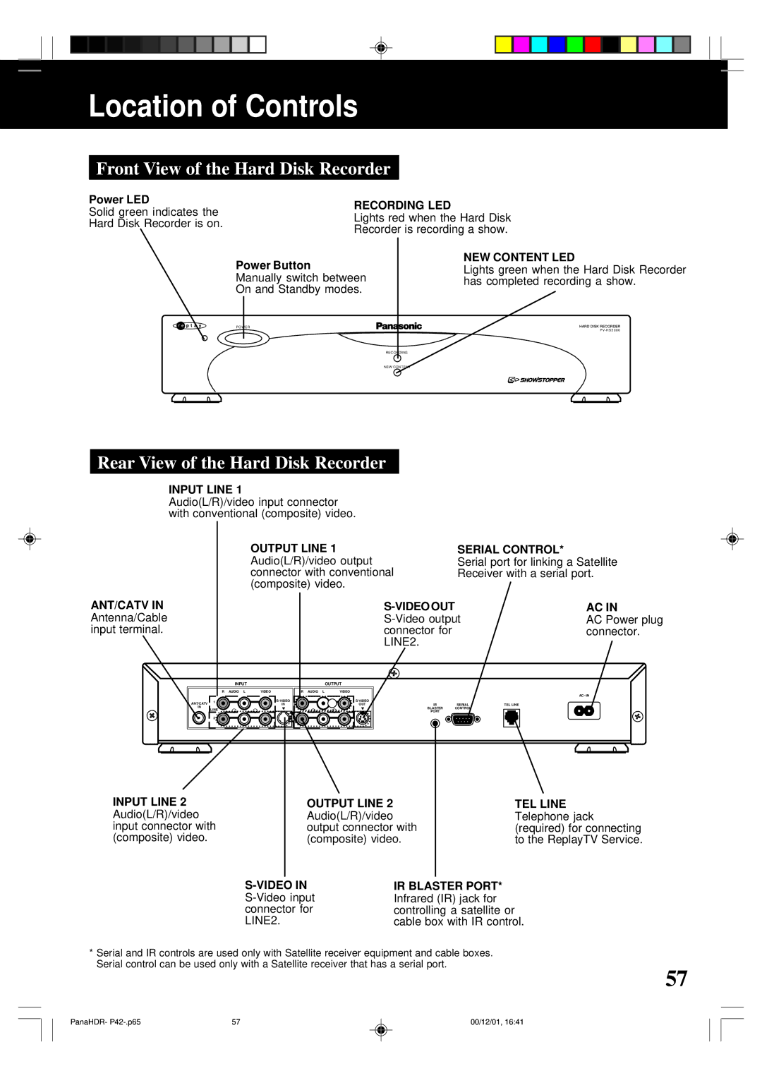
Location of Controls
Front View of the Hard Disk Recorder
Rear View of the Hard Disk Recorder
Remote Control Buttons
FF Fast Forward
33 TV/ VCR
Code Set
Volume Up/Down
Number buttons
Channel Guide
One Panasonic Way Secaucus New Jersey