| DIP Switch 1 |
| Unit |
|
| DIP Switch 1 |
| Unit |
|
| DIP Switch 1 |
| Unit | |||||||||||||||||||||
|
| Number |
|
|
| Number |
|
|
| Number | ||||||||||||||||||||||||
|
|
|
|
|
|
|
|
|
|
|
|
|
|
|
|
|
|
|
|
|
|
|
|
|
|
|
|
|
|
|
| |||
|
|
|
|
|
|
|
|
|
|
|
|
|
|
|
|
|
|
|
|
|
|
|
|
|
|
|
|
|
|
|
|
|
|
|
| ON |
|
|
|
|
|
|
|
|
|
|
| ON |
|
|
|
|
|
|
|
|
|
|
| ON |
|
|
|
|
|
|
|
|
|
| 1 | 2 | 3 | 4 | 5 | 6 | 7 | 8 |
| 69 |
|
| 1 | 2 | 3 | 4 | 5 | 6 | 7 | 8 |
| 78 |
|
| 1 | 2 | 3 | 4 | 5 | 6 | 7 | 8 |
| 87 |
|
|
|
|
|
|
|
|
|
|
|
|
|
|
|
|
|
|
|
|
|
|
|
|
|
|
|
|
|
|
|
|
|
|
|
|
|
|
|
|
|
|
|
|
|
|
|
|
|
|
|
|
|
|
|
|
|
|
|
|
|
|
|
|
|
|
|
|
|
|
| ON |
|
|
|
|
|
|
|
|
|
|
| ON |
|
|
|
|
|
|
|
|
|
|
| ON |
|
|
|
|
|
|
|
|
|
| 1 | 2 | 3 | 4 | 5 | 6 | 7 | 8 |
| 70 |
|
| 1 | 2 | 3 | 4 | 5 | 6 | 7 | 8 |
| 79 |
|
| 1 | 2 | 3 | 4 | 5 | 6 | 7 | 8 |
| 88 |
|
|
|
|
|
|
|
|
|
|
|
|
|
|
|
|
|
|
|
|
|
|
|
|
|
|
|
|
|
|
|
|
|
|
|
|
|
|
|
|
|
|
|
|
|
|
|
|
|
|
|
|
|
|
|
|
|
|
|
|
|
|
|
|
|
|
|
|
|
|
| ON |
|
|
|
|
|
|
|
|
|
|
| ON |
|
|
|
|
|
|
|
|
|
|
| ON |
|
|
|
|
|
|
|
|
|
| 1 | 2 | 3 | 4 | 5 | 6 | 7 | 8 |
| 71 |
|
| 1 | 2 | 3 | 4 | 5 | 6 | 7 | 8 |
| 80 |
|
| 1 | 2 | 3 | 4 | 5 | 6 | 7 | 8 |
| 89 |
|
|
|
|
|
|
|
|
|
|
|
|
|
|
|
|
|
|
|
|
|
|
|
|
|
|
|
|
|
|
|
|
|
|
|
|
|
|
|
|
|
|
|
|
|
|
|
|
|
|
|
|
|
|
|
|
|
|
|
|
|
|
|
|
|
|
|
|
|
|
| ON |
|
|
|
|
|
|
|
|
|
|
| ON |
|
|
|
|
|
|
|
|
|
|
| ON |
|
|
|
|
|
|
|
|
|
| 1 | 2 | 3 | 4 | 5 | 6 | 7 | 8 |
| 72 |
|
| 1 | 2 | 3 | 4 | 5 | 6 | 7 | 8 |
| 81 |
|
| 1 | 2 | 3 | 4 | 5 | 6 | 7 | 8 |
| 90 |
|
|
|
|
|
|
|
|
|
|
| ||||||||||||||||||||||||
|
|
|
|
|
|
|
|
|
|
|
|
|
|
|
|
|
|
|
|
|
|
|
|
|
|
|
|
|
|
|
|
|
|
|
| ON |
|
|
|
|
|
|
|
|
|
|
| ON |
|
|
|
|
|
|
|
|
|
|
| ON |
|
|
|
|
|
|
|
|
|
| 1 | 2 | 3 | 4 | 5 | 6 | 7 | 8 |
| 73 |
|
| 1 | 2 | 3 | 4 | 5 | 6 | 7 | 8 |
| 82 |
|
| 1 | 2 | 3 | 4 | 5 | 6 | 7 | 8 |
| 91 |
|
|
|
|
|
|
|
|
|
|
|
|
|
|
|
|
|
|
|
|
|
|
|
|
|
|
|
|
|
|
|
|
|
|
|
| ON |
|
|
|
|
|
|
|
|
|
|
| ON |
|
|
|
|
|
|
|
|
|
|
| ON |
|
|
|
|
|
|
|
|
|
| 1 | 2 | 3 | 4 | 5 | 6 | 7 | 8 |
| 74 |
|
| 1 | 2 | 3 | 4 | 5 | 6 | 7 | 8 |
| 83 |
|
| 1 | 2 | 3 | 4 | 5 | 6 | 7 | 8 |
| 92 |
|
|
|
|
|
|
|
|
|
|
| ||||||||||||||||||||||||
|
|
|
|
|
|
|
|
|
|
|
|
|
|
|
|
|
|
|
|
|
|
|
|
|
|
|
|
|
|
|
|
|
|
|
|
|
|
|
|
|
|
|
|
|
|
|
|
|
|
|
|
|
|
|
|
|
|
|
|
|
|
|
|
|
|
|
|
|
|
| ON |
|
|
|
|
|
|
|
|
|
|
| ON |
|
|
|
|
|
|
|
|
|
|
| ON |
|
|
|
|
|
|
|
|
|
| 1 | 2 | 3 | 4 | 5 | 6 | 7 | 8 |
| 75 |
|
| 1 | 2 | 3 | 4 | 5 | 6 | 7 | 8 |
| 84 |
|
| 1 | 2 | 3 | 4 | 5 | 6 | 7 | 8 |
| 93 |
|
|
|
|
|
|
|
|
|
|
| ||||||||||||||||||||||||
|
|
|
|
|
|
|
|
|
|
|
|
|
|
|
|
|
|
|
|
|
|
|
|
|
|
|
|
|
|
|
|
|
|
|
|
|
|
|
|
|
|
|
|
|
|
|
|
|
|
|
|
|
|
|
|
|
|
|
|
|
|
|
|
|
|
|
|
|
|
| ON |
|
|
|
|
|
|
|
|
|
|
| ON |
|
|
|
|
|
|
|
|
|
|
| ON |
|
|
|
|
|
|
|
|
|
| 1 | 2 | 3 | 4 | 5 | 6 | 7 | 8 |
| 76 |
|
| 1 | 2 | 3 | 4 | 5 | 6 | 7 | 8 |
| 85 |
|
| 1 | 2 | 3 | 4 | 5 | 6 | 7 | 8 |
| 94 |
|
|
|
|
|
|
|
|
|
|
| ||||||||||||||||||||||||
|
|
|
|
|
|
|
|
|
|
|
|
|
|
|
|
|
|
|
|
|
|
|
|
|
|
|
|
|
|
|
|
|
|
|
| ON |
|
|
|
|
|
|
|
|
|
|
| ON |
|
|
|
|
|
|
|
|
|
|
| ON |
|
|
|
|
|
|
|
|
|
| 1 | 2 | 3 | 4 | 5 | 6 | 7 | 8 |
| 77 |
|
| 1 | 2 | 3 | 4 | 5 | 6 | 7 | 8 |
| 86 |
|
| 1 | 2 | 3 | 4 | 5 | 6 | 7 | 8 |
| 95 |
|
|
|
|
|
|
|
|
|
|
| ||||||||||||||||||||||||
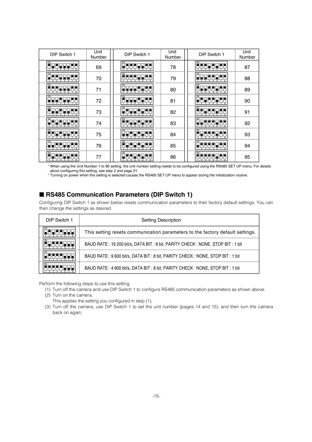
*When using the Unit Number 1 to 96 setting, the unit number setting needs to be configured using the RS485 SET UP menu. For details about configuring this setting, see step 2 and page 21.
*Turning on power when this setting is selected causes the RS485 SET UP menu to appear during the initialization routine.
■RS485 Communication Parameters (DIP Switch 1)
Configuring DIP Switch 1 as shown below resets communication parameters to their factory default settings. You can then change the settings as desired.
| DIP Switch 1 |
| Setting Description | |||||||
|
|
|
|
|
|
|
|
|
|
|
|
|
|
|
|
|
|
|
|
|
|
| ON |
|
|
|
|
|
|
|
| This setting resets communication parameters to the factory default settings. |
| 1 | 2 | 3 | 4 | 5 | 6 | 7 | 8 |
| |
|
|
| ||||||||
|
|
|
|
|
|
|
|
|
|
|
|
|
|
|
|
|
|
|
|
|
|
| ON |
|
|
|
|
|
|
|
| BAUD RATE : 19 200 bit/s, DATA BIT : 8 bit, PARITY CHECK : NONE, STOP BIT : 1 bit |
| 1 | 2 | 3 | 4 | 5 | 6 | 7 | 8 |
| |
|
|
| ||||||||
|
|
|
|
|
|
|
|
|
|
|
|
|
|
|
|
|
|
|
|
|
|
| ON |
|
|
|
|
|
|
|
| BAUD RATE : 9 600 bit/s, DATA BIT : 8 bit, PARITY CHECK : NONE, STOP BIT : 1 bit |
| 1 | 2 | 3 | 4 | 5 | 6 | 7 | 8 |
| |
|
|
| ||||||||
|
|
|
|
|
|
|
|
|
|
|
|
|
|
|
|
|
|
|
|
|
|
| ON |
|
|
|
|
|
|
|
| BAUD RATE : 4 800 bit/s, DATA BIT : 8 bit, PARITY CHECK : NONE, STOP BIT : 1 bit |
| 1 | 2 | 3 | 4 | 5 | 6 | 7 | 8 |
| |
|
|
| ||||||||
|
|
|
|
|
|
|
|
|
|
|
Perform the following steps to use this setting.
(1)Turn off the camera and use DIP Switch 1 to configure RS485 communication parameters as shown above.
(2)Turn on the camera.
This applies the setting you configured in step (1).
(3)Turn off the camera, use DIP Switch 1 to set the unit number (pages 14 and 15), and then turn the camera back on again.