PANDUIT DPoE Power System User’s Guide | Issue 1.0 |
| Part Number: PN380 |
CAUTION:
ALWAYS FOLLOW NEC GUIDELINES AND YOUR LOCAL COMPANY PRACTICES WHEN SELECTING DC WIRING AND PROTECTION.
Table 5: Minimum Recommended DC AWG for 90° C Cabling for Unprotected Outputs shows recommended wire sizes based on ampacity. The maximum current rating for the chassis is 100 A.
1 2
14
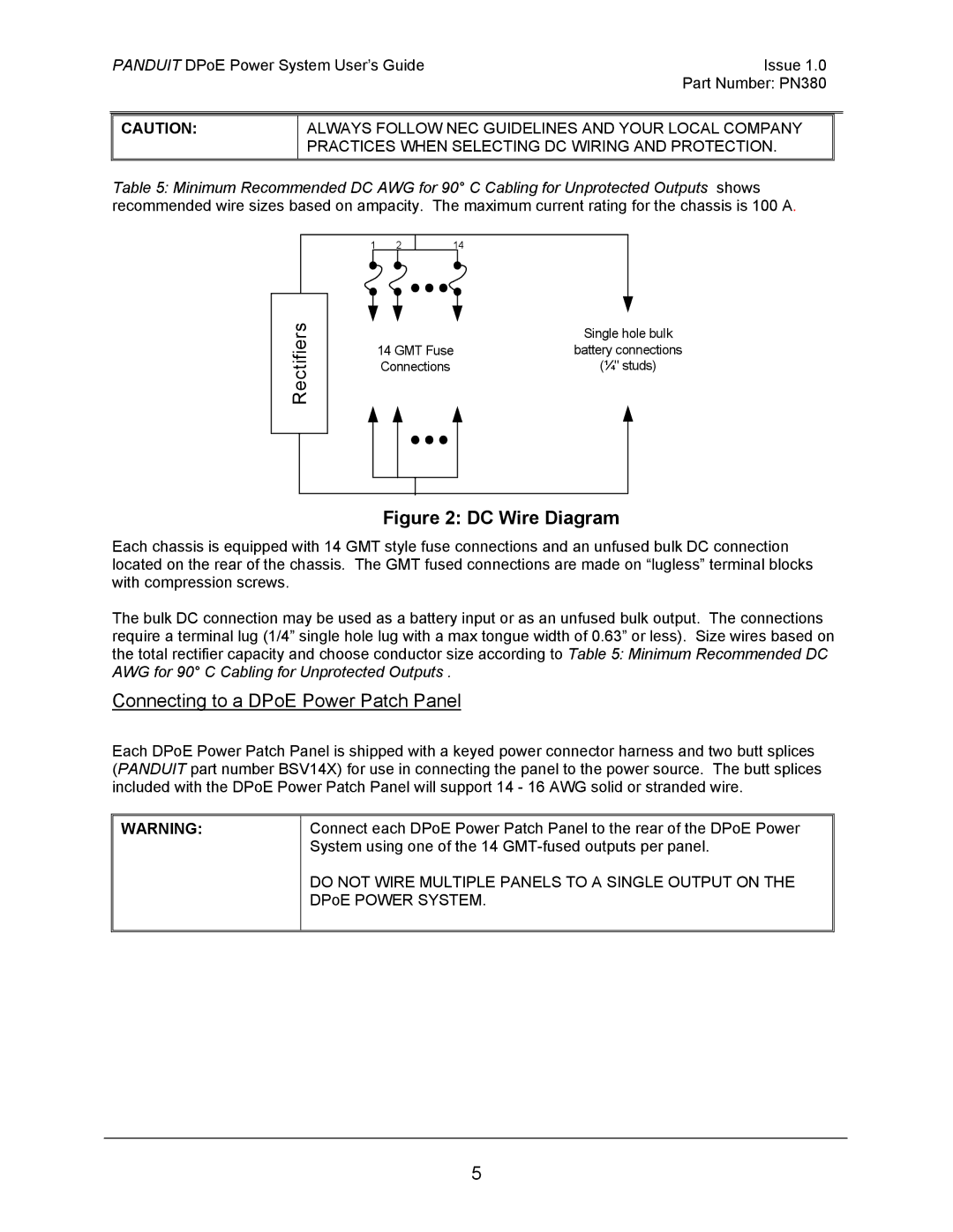
Rectifiers
| Single hole bulk |
14 GMT Fuse | battery connections |
Connections | (¼" studs) |
Figure 2: DC Wire Diagram
Each chassis is equipped with 14 GMT style fuse connections and an unfused bulk DC connection located on the rear of the chassis. The GMT fused connections are made on “lugless” terminal blocks with compression screws.
The bulk DC connection may be used as a battery input or as an unfused bulk output. The connections require a terminal lug (1/4” single hole lug with a max tongue width of 0.63” or less). Size wires based on the total rectifier capacity and choose conductor size according to Table 5: Minimum Recommended DC AWG for 90° C Cabling for Unprotected Outputs .
Connecting to a DPoE Power Patch Panel
Each DPoE Power Patch Panel is shipped with a keyed power connector harness and two butt splices (PANDUIT part number BSV14X) for use in connecting the panel to the power source. The butt splices included with the DPoE Power Patch Panel will support 14 - 16 AWG solid or stranded wire.
WARNING:
Connect each DPoE Power Patch Panel to the rear of the DPoE Power System using one of the 14
DO NOT WIRE MULTIPLE PANELS TO A SINGLE OUTPUT ON THE DPoE POWER SYSTEM.
5