PANDUIT DPoE Power System User’s Guide | Issue 1.0 |
| Part Number: PN380 |
|
|
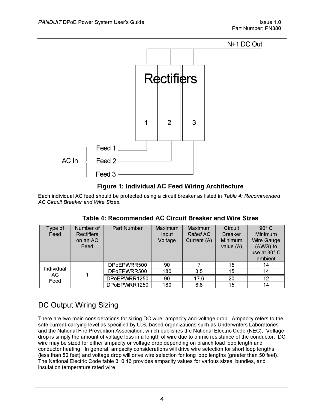
| N+1 DC Out |
Rectifiers
1
2
3
Feed 1
AC In | Feed 2 |
Feed 3
Figure 1: Individual AC Feed Wiring Architecture
Each individual AC feed should be protected using a circuit breaker as listed in Table 4: Recommended AC Circuit Breaker and Wire Sizes.
Table 4: Recommended AC Circuit Breaker and Wire Sizes
| Type of |
| Number of |
|
| Part Number | Maximum |
| Maximum |
| Circuit |
| 90° C |
|
| Feed |
| Rectifiers |
|
|
| Input |
| Rated AC |
| Breaker |
| Minimum |
|
|
|
| on an AC |
|
|
| Voltage |
| Current (A) |
| Minimum |
| Wire Gauge |
|
|
|
| Feed |
|
|
|
|
|
|
| value (A) |
| (AWG) to |
|
|
|
|
|
|
|
|
|
|
|
|
|
| use at 30° C |
|
|
|
|
|
|
|
|
|
|
|
|
|
| ambient |
|
| Individual |
|
|
|
| DPoEPWRR500 | 90 |
| 7 |
| 15 |
| 14 |
|
|
| 1 |
|
| DPoEPWRR500 | 180 |
| 3.5 |
| 15 |
| 14 |
| |
| AC |
|
|
|
|
|
|
| ||||||
|
|
|
| DPoEPWRR1250 | 90 |
| 17.6 |
| 20 |
| 12 |
| ||
| Feed |
|
|
|
|
|
|
|
| |||||
|
|
|
|
| DPoEPWRR1250 | 180 |
| 8.8 |
| 15 |
| 14 |
| |
|
|
|
|
|
|
|
|
|
|
DC Output Wiring Sizing
There are two main considerations for sizing DC wire: ampacity and voltage drop. Ampacity refers to the safe
4