PANDUIT DPoE Power System User’s Guide | Issue 1.0 |
| Part Number: PN380 |
Table 7: PANDUIT Corporation Contact Information
PANDUIT Technical Support | Fax: |
| |
|
|
For Installation Instructions in Local Languages | www.panduit.com/resources/install_maintain.asp |
and Technical Support |
|
|
|
Worldwide Subsidiaries and Sales Offices | www.panduit.com |
|
|
Have all tools, wire, cables, hardware, etc., within easy reach. To the extent possible, ensure a clean (free of debris, dust, foreign material, etc.) work environment. Care should be taken in the installation process to prevent wire clippings from getting into the equipment.
NOTE:
If possible, the rectifiers should remained sealed in their shipping boxes until the chassis wiring is complete.
Power Plant Mounting and Wiring
![]()
![]() WARNING:
WARNING:
Ensure all AC and DC power sources are off and disconnected.
Mechanical Mounting
The DPoE Power System chassis is installed in a standard EIA 19” rack.
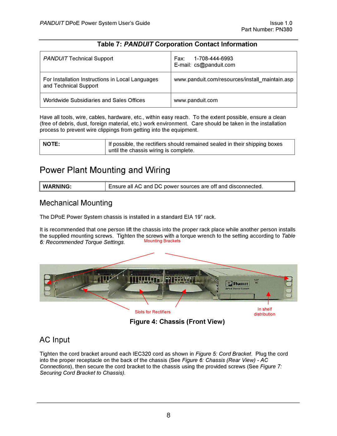
It is recommended that one person lift the chassis into the proper rack place while another person installs the supplied mounting screws. Tighten the screws with a torque wrench to the setting according to Table
6: Recommended Torque Settings. | Mounting Brackets |
Slots for Rectifiers | In shelf | |
distribution | ||
|
Figure 4: Chassis (Front View)
AC Input
Tighten the cord bracket around each IEC320 cord as shown in Figure 5: Cord Bracket. Plug the cord
into the proper receptacle on the back of the chassis (See Figure 6: Chassis (Rear View) - AC Connections), then secure the cord bracket to the chassis using the provided screws (See Figure 7: Securing Cord Bracket to Chassis).
8