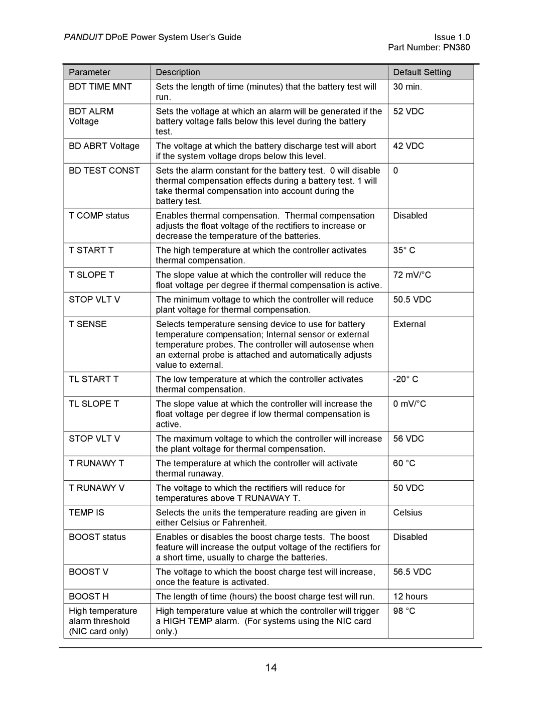
|
| PANDUIT DPoE Power System User’s Guide | Issue 1.0 |
| ||
|
|
|
| Part Number: PN380 |
| |
|
|
|
|
|
|
|
|
| Parameter | Description | Default Setting |
|
|
|
| BDT TIME MNT | Sets the length of time (minutes) that the battery test will | 30 min. |
|
|
|
|
| run. |
|
|
|
|
| BDT ALRM | Sets the voltage at which an alarm will be generated if the | 52 VDC |
|
|
|
| Voltage | battery voltage falls below this level during the battery |
|
|
|
|
|
| test. |
|
|
|
|
| BD ABRT Voltage | The voltage at which the battery discharge test will abort | 42 VDC |
|
|
|
|
| if the system voltage drops below this level. |
|
|
|
|
| BD TEST CONST | Sets the alarm constant for the battery test. 0 will disable | 0 |
|
|
|
|
| thermal compensation effects during a battery test. 1 will |
|
|
|
|
|
| take thermal compensation into account during the |
|
|
|
|
|
| battery test. |
|
|
|
|
| T COMP status | Enables thermal compensation. Thermal compensation | Disabled |
|
|
|
|
| adjusts the float voltage of the rectifiers to increase or |
|
|
|
|
|
| decrease the temperature of the batteries. |
|
|
|
|
| T START T | The high temperature at which the controller activates | 35° C |
|
|
|
|
| thermal compensation. |
|
|
|
|
| T SLOPE T | The slope value at which the controller will reduce the | 72 mV/°C |
|
|
|
|
| float voltage per degree if thermal compensation is active. |
|
|
|
|
| STOP VLT V | The minimum voltage to which the controller will reduce | 50.5 VDC |
|
|
|
|
| plant voltage for thermal compensation. |
|
|
|
|
| T SENSE | Selects temperature sensing device to use for battery | External |
|
|
|
|
| temperature compensation; Internal sensor or external |
|
|
|
|
|
| temperature probes. The controller will autosense when |
|
|
|
|
|
| an external probe is attached and automatically adjusts |
|
|
|
|
|
| value to external. |
|
|
|
|
| TL START T | The low temperature at which the controller activates |
|
| |
|
|
| thermal compensation. |
|
|
|
|
| TL SLOPE T | The slope value at which the controller will increase the | 0 mV/°C |
|
|
|
|
| float voltage per degree if low thermal compensation is |
|
|
|
|
|
| active. |
|
|
|
|
| STOP VLT V | The maximum voltage to which the controller will increase | 56 VDC |
|
|
|
|
| the plant voltage for thermal compensation. |
|
|
|
|
| T RUNAWY T | The temperature at which the controller will activate | 60 °C |
|
|
|
|
| thermal runaway. |
|
|
|
|
| T RUNAWY V | The voltage to which the rectifiers will reduce for | 50 VDC |
|
|
|
|
| temperatures above T RUNAWAY T. |
|
|
|
|
| TEMP IS | Selects the units the temperature reading are given in | Celsius |
|
|
|
|
| either Celsius or Fahrenheit. |
|
|
|
|
| BOOST status | Enables or disables the boost charge tests. The boost | Disabled |
|
|
|
|
| feature will increase the output voltage of the rectifiers for |
|
|
|
|
|
| a short time, usually to charge the batteries. |
|
|
|
|
| BOOST V | The voltage to which the boost charge test will increase, | 56.5 VDC |
|
|
|
|
| once the feature is activated. |
|
|
|
|
| BOOST H | The length of time (hours) the boost charge test will run. | 12 hours |
|
|
|
|
|
|
|
|
|
|
| High temperature | High temperature value at which the controller will trigger | 98 °C |
|
|
|
| alarm threshold | a HIGH TEMP alarm. (For systems using the NIC card |
|
|
|
|
| (NIC card only) | only.) |
|
|
|
|
|
|
|
|
|
|
14
