PANDUIT DPoE Power System User’s Guide | Issue 1.0 |
| Part Number: PN380 |
Short Circuit and Current Limit
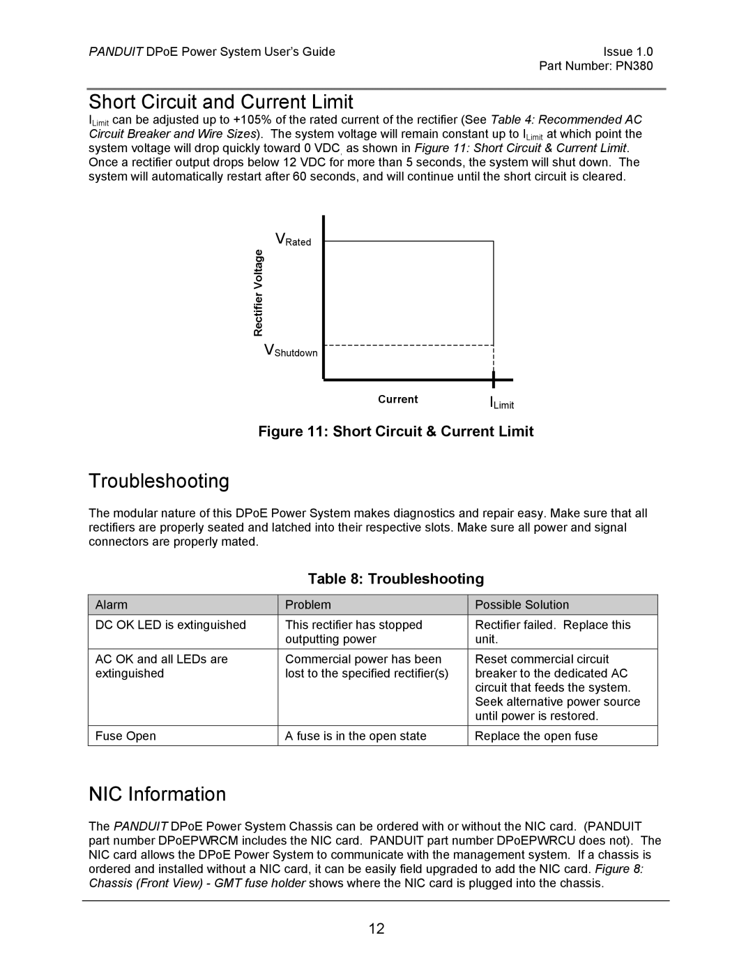
ILimit can be adjusted up to +105% of the rated current of the rectifier (See Table 4: Recommended AC Circuit Breaker and Wire Sizes). The system voltage will remain constant up to ILimit at which point the system voltage will drop quickly toward 0 VDC, as shown in Figure 11: Short Circuit & Current Limit.
Once a rectifier output drops below 12 VDC for more than 5 seconds, the system will shut down. The system will automatically restart after 60 seconds, and will continue until the short circuit is cleared.
VRated
Rectifier Voltage
VShutdown
CurrentILimit
Figure 11: Short Circuit & Current Limit
Troubleshooting
The modular nature of this DPoE Power System makes diagnostics and repair easy. Make sure that all rectifiers are properly seated and latched into their respective slots. Make sure all power and signal connectors are properly mated.
Table 8: Troubleshooting
Alarm | Problem | Possible Solution |
DC OK LED is extinguished | This rectifier has stopped | Rectifier failed. Replace this |
| outputting power | unit. |
AC OK and all LEDs are | Commercial power has been | Reset commercial circuit |
extinguished | lost to the specified rectifier(s) | breaker to the dedicated AC |
|
| circuit that feeds the system. |
|
| Seek alternative power source |
|
| until power is restored. |
Fuse Open | A fuse is in the open state | Replace the open fuse |
NIC Information
The PANDUIT DPoE Power System Chassis can be ordered with or without the NIC card. (PANDUIT part number DPoEPWRCM includes the NIC card. PANDUIT part number DPoEPWRCU does not). The NIC card allows the DPoE Power System to communicate with the management system. If a chassis is ordered and installed without a NIC card, it can be easily field upgraded to add the NIC card. Figure 8: Chassis (Front View) - GMT fuse holder shows where the NIC card is plugged into the chassis.
12