PANDUIT DPoE Power System User’s Guide | Issue 1.0 |
| Part Number: PN380 |
Ethernet Connections
The Ethernet port on the back of the DPoE Power System chassis is used to provide the connection between the NIC card and the management system.
Test and Turn-Up
Power Up
Once all AC and DC connections have been secured and checked, install each rectifier sequentially by sliding and latching it into the chassis as illustrated in the section below.
Rectifiers
The rectifiers for use in the DPoE Power System are equipped with Light Emitting Diodes (LEDs) on the front panel as a means to indicate problems with that specific rectifier. The rectifiers are designed as modular, field replaceable units.
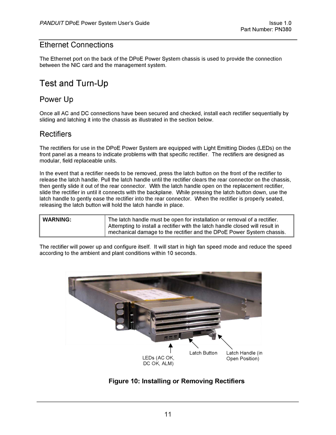
In the event that a rectifier needs to be removed, press the latch button on the front of the rectifier to release the latch handle. Pull the latch handle until the rectifier clears the rear connector on the chassis, then gently slide it out of the rear connector. With the latch handle open on the replacement rectifier, slide the rectifier in until it connects with the backplane. While pressing the latch button down, use the latch handle to gently ease the rectifier into the rear connector. When the rectifier is properly seated, releasing the latch button will hold the latch handle in place.
WARNING:
The latch handle must be open for installation or removal of a rectifier. Attempting to install a rectifier with the latch handle closed will result in mechanical damage to the rectifier and the DPoE Power System chassis.
The rectifier will power up and configure itself. It will start in high fan speed mode and reduce the speed according to the ambient and plant conditions within 10 seconds.
| Latch Button | Latch Handle (in |
| ||
LEDs (AC OK, | Open Position) | |
DC OK, ALM) |
| |
Figure 10: Installing or Removing Rectifiers
11