| 23 |
|
38 |
|
|
12 |
|
|
91 |
|
|
3/8 X |
|
|
| 61 |
|
|
| 63 |
| 51 | 108 |
| 64 3/8 X | |
|
| HEAD CAP SCREW |
| 3/8” HEX NUT 108 | DETAIL 32 |
| 63 | |
FIGURE 32 |
| |
64 3/8 X | ||
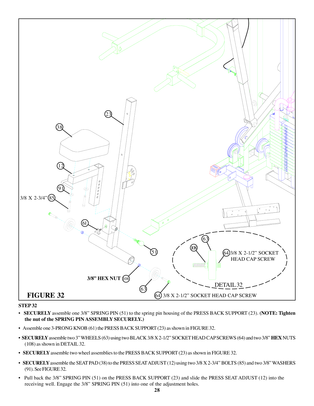
STEP 32
•SECURELY assemble one 3/8” SPRING PIN (51) to the spring pin housing of the PRESS BACK SUPPORT (23). (NOTE: Tighten the nut of the SPRING PIN ASSEMBLY SECURELY.)
•Assemble one
•SECURELYassemble two 3” WHEELS (63) using two BLACK 3/8 X
(108)as shown in DETAIL 32.
•SECURELY assemble two wheel assemblies to the PRESS BACK SUPPORT (23) as shown in FIGURE 32.
•SECURELY assemble the SEAT PAD (38) to the PRESS SEATADJUST (12) using two 3/8 X
(91).See FIGURE 32.
•Pull back the 3/8” SPRING PIN (51) on the PRESS BACK SUPPORT (23) and slide the PRESS SEAT ADJUST (12) into the receiving well. Engage the 3/8” SPRING PIN (51) into one of the adjustment holes.
28