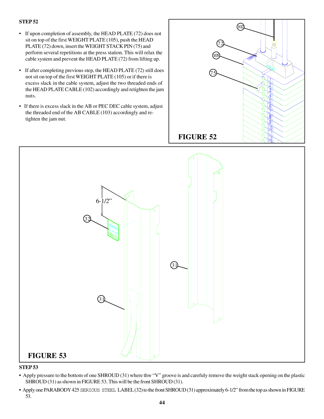
STEP 52
•If upon completion of assembly, the HEAD PLATE (72) does not sit on top of the first WEIGHT PLATE (105), push the HEAD PLATE (72) down, insert the WEIGHT STACK PIN (75) and perform several repetitions at the press station. This will relax the cable system and prevent the HEAD PLATE (72) from lifting up.
•If after completing previous step, the HEAD PLATE (72) still does not sit on top of the first WEIGHT PLATE (105) or if there is excess slack in the cable system, adjust the two threaded ends of the HEAD PLATE CABLE (102) accordingly and retighten the jam nuts.
•If there is excess slack in the AB or PEC DEC cable system, adjust the threaded end of the AB CABLE (103) accordingly and re- tighten the jam nut.
102 |
72 |
105 |
75 |
FIGURE 52 |
32
31
31
FIGURE 53
STEP 53
•Apply pressure to the bottom of one SHROUD (31) where thw “V” groove is and carefuly remove the weight stack opening on the plastic SHROUD (31) as shown in FIGURE 53. This will be the front SHROUD (31).
•Apply one PARABODY425 SERIOUS STEEL LABEL(32) to the front SHROUD (31) approximately
44