17 |
102 |
7 |
73 |
72 |
FIGURE 35 |
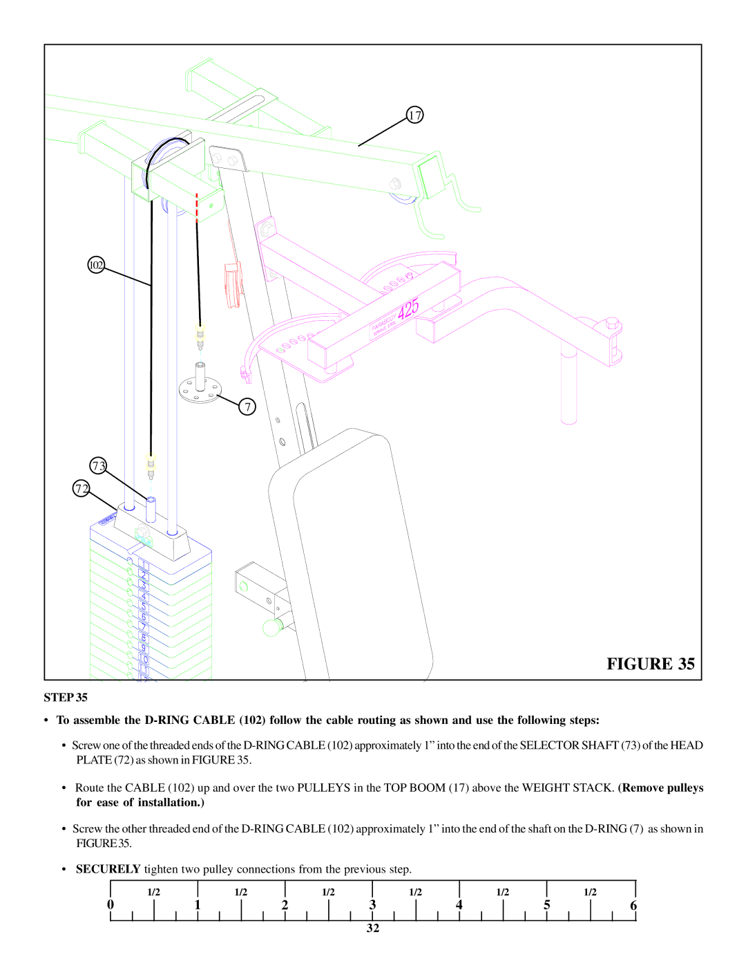
STEP 35
•To assemble the
•Screw one of the threaded ends of the
•Route the CABLE (102) up and over the two PULLEYS in the TOP BOOM (17) above the WEIGHT STACK. (Remove pulleys for ease of installation.)
•Screw the other threaded end of the
•SECURELY tighten two pulley connections from the previous step.
| 1/2 |
| 1/2 |
| 1/2 |
| 1/2 |
| 1/2 |
|
| 1/2 |
0 | 1 | 2 | 3 | 4 | 5 | 6 | ||||||
32