| 85 3/8 X |
|
49 |
|
|
|
| 3/8 X |
| 17 | 49 |
|
| |
49 |
|
|
92 | 49 |
|
|
| |
| 92 |
|
42 |
| 42 |
|
| |
FIGURE 11 |
|
|
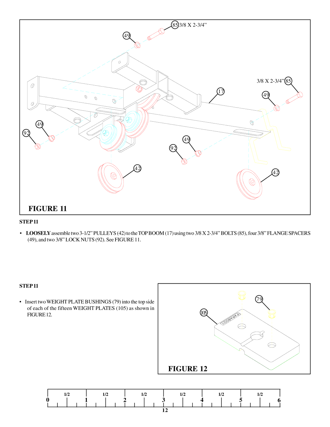
STEP 11
•LOOSELYassemble two
STEP 11
•Insert two WEIGHT PLATE BUSHINGS (79) into the top side of each of the fifteen WEIGHT PLATES (105) as shown in FIGURE12.
79
105
FIGURE 12
| 1/2 |
| 1/2 |
| 1/2 |
| 1/2 |
| 1/2 |
|
| 1/2 |
0 | 1 | 2 | 3 | 4 | 5 | 6 | ||||||
12