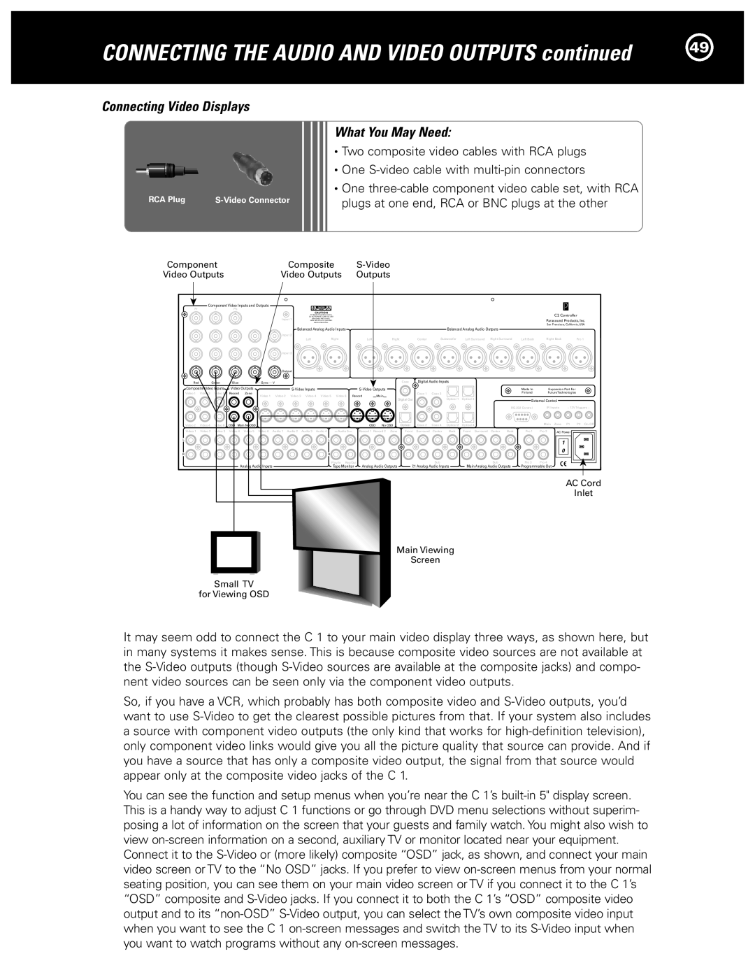
Halo C1 Controller specifications
The Parasound Halo C1 Controller emerges as a premium choice for audio enthusiasts seeking high-performance home theater solutions. This exceptional product combines innovative technology with user-friendly features, ensuring an unparalleled listening experience for both music and movie lovers.At its core, the Halo C1 Controller serves as a powerful preamplifier and processor, designed to manage and control audio and video signals effectively. It is equipped with a balanced XLR input and multiple RCA inputs, allowing seamless integration with various audio sources. With support for high-resolution audio formats, including PCM and DSD, the Halo C1 delivers pristine sound quality that enhances the listening experience.
One of the defining characteristics of the Halo C1 is its advanced digital processing capabilities. The unit features Dolby Digital and DTS decoding, along with several proprietary audio technologies that elevate its performance. Its ability to upmix stereo signals into multi-channel formats contributes to an immersive surround sound experience, making it an ideal companion for both music playback and movie watching.
The Halo C1 also boasts an intuitive user interface, complete with an easy-to-navigate on-screen display. This feature simplifies the setup and configuration process, allowing users to personalize their audio experience to suit their preferences. For added convenience, the C1 supports remote control operation, enabling users to adjust settings without leaving their seats.
In terms of connectivity, the Halo C1 provides an impressive array of options. It includes HDMI inputs and outputs, ensuring compatibility with modern AV equipment and facilitating the transmission of high-definition video alongside high-fidelity audio. Additionally, it features variable and fixed outputs, making it adaptable for different system configurations.
Another standout feature of the Halo C1 is its robust power supply. The unit employs a toroidal transformer, ensuring clean and stable power delivery that translates into superior sound performance. This design choice minimizes power supply noise, which can adversely affect audio quality.
In conclusion, the Parasound Halo C1 Controller is a sophisticated and versatile audio solution that caters to both audiophiles and home theater enthusiasts. With its exceptional performance, advanced technology, and user-friendly features, the Halo C1 stands out as a key component for creating a high-quality audio and video experience in any home entertainment system. Its ability to adapt and enhance the listening experience makes it a worthy investment for anyone serious about sound quality.

